Eureka AIR delivers breakthrough ideas for toughest innovation challenges, trusted by R&D personnel around the world.

Non-return valve for a petrochemical reactor

A petrochemical and reactor technology, applied in the field of one-way devices, can solve problems such as increased man-hours and costs, and difficulty in disassembling

Inactive Publication Date: 2007-12-12
诺沃皮尼奥内控股有限公司
View PDF2 Cites 0 Cited by
  • Summary
  • Abstract
  • Description
  • Claims
  • Application Information

AI Technical Summary

Problems solved by technology

[0009] In fact, as mentioned above, solid residues of the process fluid penetrate between the contact surfaces of the cartridge and the support tube, bonding the two parts together and making them difficult to disassemble
Therefore, the operator has to frequently replace the entire device, which increases man-hours and costs.

Method used


Image

  • Non-return valve for a petrochemical reactor
  • Non-return valve for a petrochemical reactor

Examples


Embodiment Construction

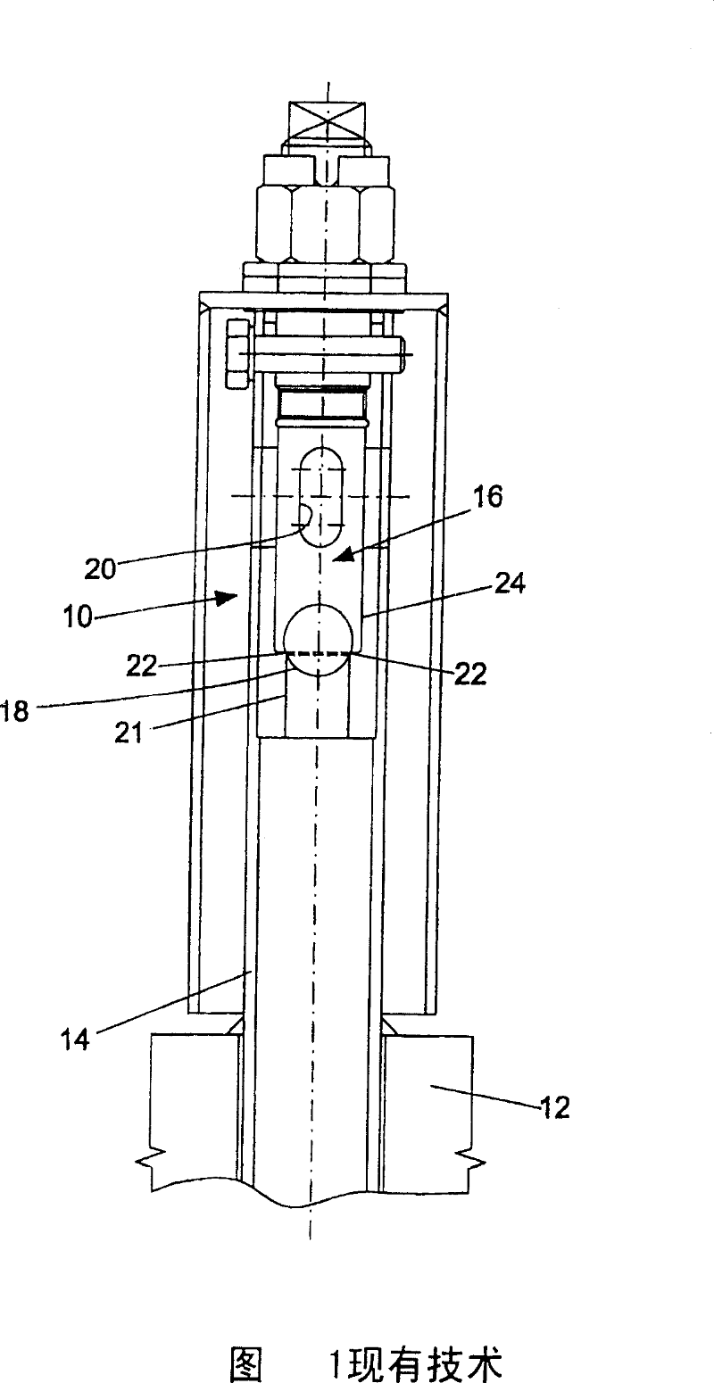
[0030] Referring to Figure 1, there is shown a one-way unit 10 for a petrochemical refinery reactor 12 according to known techniques.

[0031] The one-way unit 10 includes a support tube 14 connected to a portion of the reactor 12 . A cylindrical barrel 16 containing balls 18 is mounted within the support tube.

[0032] The cartridge 16 has lateral slots 20 for the outflow of process fluid. The fluid also passes through corresponding holes in the support tube 14 inserted into the cartridge 16 .

[0033] The barrel 16 has, at its lower end portion, around the inlet opening 21 for the process fluid, a seat 22 for receiving the ball 18 .

[0034] As can be seen in the example of FIG. 1, the support tube 14 is welded to a part of the reactor 12 in a vertical position. Alternatively, this support tube 14 can be secured by mechanical means.

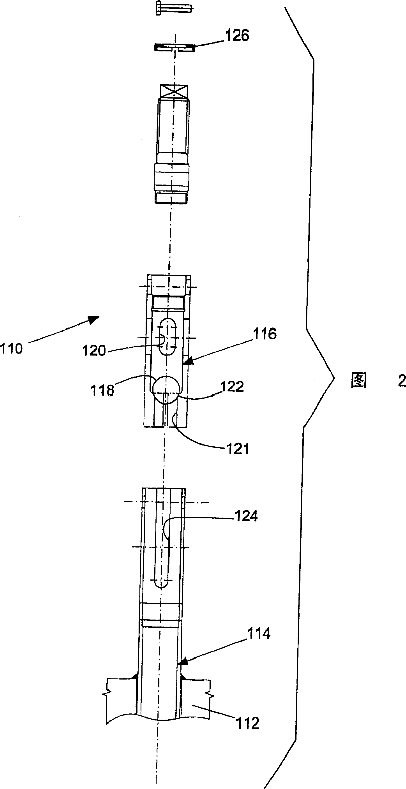
[0035] Figure 2 shows a quick replaceable one-way device 110 for a petrochemical refinery reactor 112 according to the present invention. ...


PUM


Abstract

A rapidly replaceable non-return device (110) for a petrochemical refinery reactor (112), of the type comprising a support tube (114), connected to a portion of the reactor (112), this support tube (114) being provided internally with a cartridge (116) containing a ball (118), the cartridge (116) having, around an inlet hole (121) for a processed fluid, a seat (122) for housing the ball (118), and having slots (120) for the outflow of the said processed fluid; the cartridge (116) is fitted removably in the support tube (114).

Description

technical field [0001] The invention relates to a rapidly replaceable one-way device for petrochemical refinery reactors. Background technique [0002] In petroleum refining reactors in some petrochemical processes, cylindrical devices are used as check valves. These devices allow the flow of product undergoing refining processes in one direction while preventing reverse flow of product and any catalyst particles that would damage equipment upstream of the device. [0003] In current technical language, these cylindrical devices are called "standpipes". [0004] Their operation is simple: each device has a terminal section that houses a ball that is pushed by the fluid pressure of the process fluid and moves axially until it emerges from a radial slot through which the fluid can exit . [0005] Back pressure pushes the ball against an appropriately shaped housing to create a seal against reverse flow. [0006] Apparently, the axial and radial movement of the balls causes...

Claims


Application Information

Patent Timeline
IPC IPC(8): B01J8/24F16K15/04F16K27/02
CPCF16K27/0245F16K15/04B01J8/1872Y10T137/7504Y10T137/791B01J8/18B01J8/24
Inventor M·贾科梅利E·拉泽里尼S·里奇
Owner 诺沃皮尼奥内控股有限公司
Why Eureka
Eureka Blog
Learn More