


Quick Research
Generate reliable direction feasibility study reports for your R&D in just a few steps.

Technical Q&A
Discover and master advanced knowledge NOW. Basics, ideas, possibilities, all at once.

Find Solutions
As an expert in R&D theories, this can generate solutions to your technical problems instantly.

Evaluate Feasibility
Analyze your overall solution with one click, know your potential R&D risks in advance.

Monitor Landscape
Get weekly tech updates, stay abreast of the latest tech innovations and key insights.
Melt processible fluoropolymer composition
A technology of melt processing and composition, which is applied in the field of melt processable fluoropolymer compositions, and can solve problems such as difficulty in making block copolymers
- Summary
- Abstract
- Description
- Claims
- Application Information
AI Technical Summary
Problems solved by technology
Method used
Image

Examples
Embodiment
[0022] The following examples are given for the purpose of illustration. In the following, the raw materials used in the examples and comparative examples and the evaluation methods adopted for the physical properties of the finished compositions are described.
[0023] (1) Polymer
[0024] The melt-processable fluoropolymers used in the Examples and Comparative Examples are summarized in Table 1, along with their comonomer composition and melt flow rate. In the table, TFE / HFP-2 is a copolymer of TFE and HFP; TFE / HFP-3 is a terpolymer of TFE, HFP and PEVE. PFA-C2 is a copolymer of TFE and PEVE.
[0025] Table 1
[0026] Fluoropolymer
Comonomer content (wt%)
MFR(g / 10min)
TFE / HFP-2(A)
TFE / HFP-3(B)
TFE / HFP-3(C)
PFA-C2(D)
PFA-C2(E)
PFA-C2(F)
HFP12%
HFP11.5%; PEVE1.2%
HFP6.5%; PEVE1.8%
PEVE 13.3%
PEVE 7.1%
PEVE 5.7%
24
22
23
10
19
23
[0027] MFR: Melt flow rate, measured in accordance with AST...
example 1~3 and comparative example 1~6
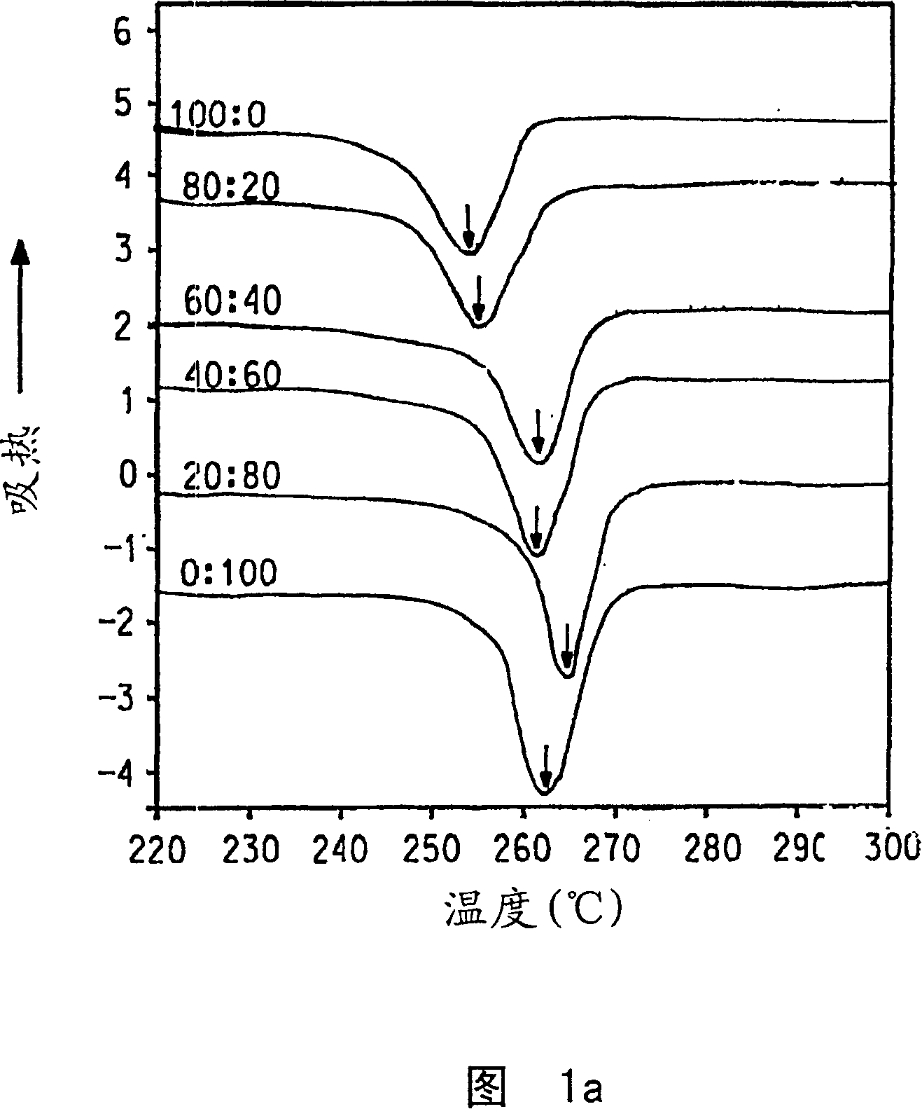
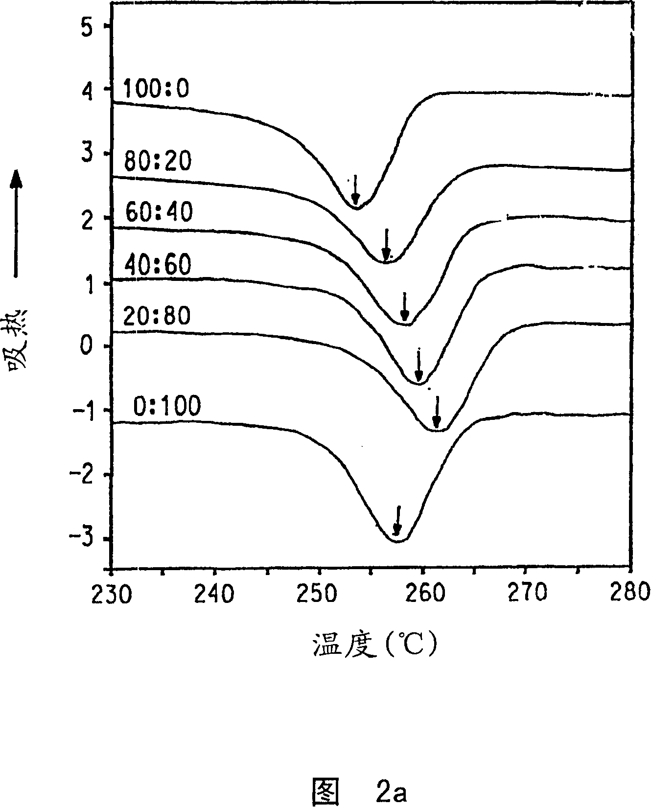
[0038] A melt blend of TFE / HFP-2 or TFE / HFP-3 and PFA at a weight ratio of 60 / 40 was used to investigate the difference in miscibility under different comonomer composition conditions. The results are summarized in Tables 2A and 2B. When the molten blend shows a single crystallization peak during crystallization and a single melting point appears between the melting points of the individual components during the temperature rise of the crystalline mixture, the mixture is judged to be a miscible blend in the crystallization zone and the components occur. A co-crystallization.
[0039] Table 2A
[0040] Comparison
1
2
3
4
5
6
TFE / HFP-2
(A)
TFE / HFP-3
(B)
TFE / HFP-3
(C)
PFA-C2(D)
PFA-C2(E)
PFA-C2(F)
Crystallization temperature
60
40
double
double
Immiscible
60
40
double
double
Immiscible
60
...
example 4~7, comparative example 7 and 8
[0047] Prepare a molten blend. The measured value of flex life is obtained by using a sample made of the obtained composition through compression molding. The results are shown in Table 3. The mixture of PFA-C2(E) and TFE / HFP-3(C) significantly improves the flex life.
[0048] The melt strength of the above-mentioned sample composition was measured with a Capilograph at 370°C. The results are shown in Table 3. Since the purpose is to improve the high-speed spinning performance of TFE / HFP, the melt strength measurement is only performed on a mixture with a TFE / HFP content of at least 60%. The blending of PFA-C2 (E) and TFE / HFP-3 (C) produces blends with improved melt strength.
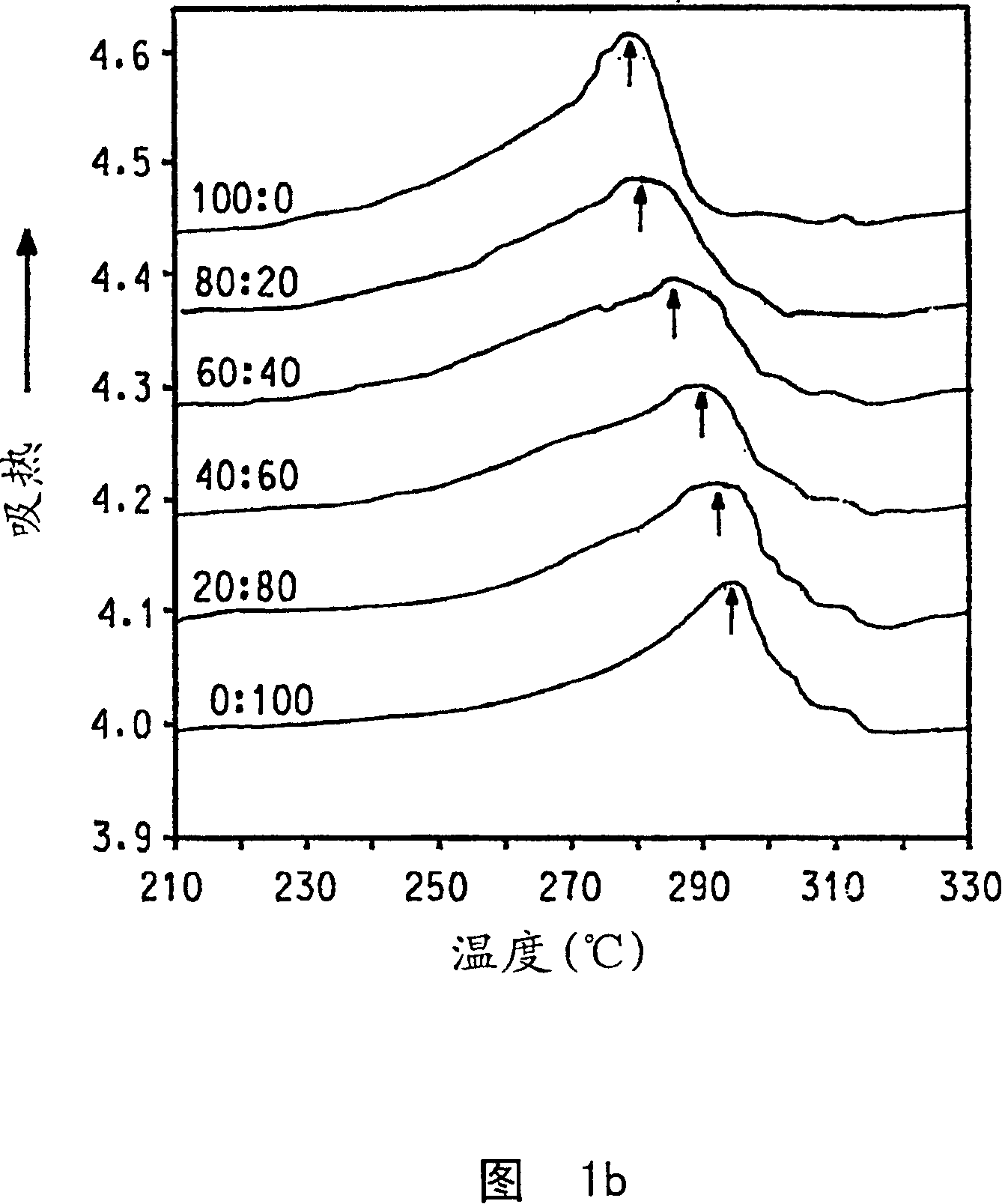
[0049] The DSC measurement results and DSC chart of the compositions prepared in these examples are summarized in Table 3 and Figures 1(a) and 1(b). As is clearly seen from Figure 1, the TFE / HFP-3(C) / PFA-C2(E) blend shows a single crystallization temperature and a single melting peak in all ratios, indicati...
PUM
 Abstract
Description
Claims
Application Information
 - R&D Engineer
- R&D Manager
- IP Professional
- Industry Leading Data Capabilities
- Powerful AI technology
- Patent DNA Extraction
Browse by: Latest US Patents, China's latest patents, Technical Efficacy Thesaurus, Application Domain, Technology Topic, Popular Technical Reports.
© 2024 PatSnap. All rights reserved.Legal|Privacy policy|Modern Slavery Act Transparency Statement|Sitemap|About US| Contact US: help@patsnap.com