Optical fiber micro-bending displacement sensor

A displacement sensor and optical fiber coupler technology, which is applied in the sensor field in the field of testing technology to achieve the effects of extending service life, small shear deformation, and improving dynamic performance

Inactive Publication Date: 2008-01-09
SHANGHAI JIAO TONG UNIV
View PDF9 Cites 0 Cited by
  • Summary
  • Abstract
  • Description
  • Claims
  • Application Information

AI Technical Summary

Problems solved by technology

Both fiber rings are connected to the same optical power meter

Method used


Image

  • Optical fiber micro-bending displacement sensor

Examples


Embodiment Construction

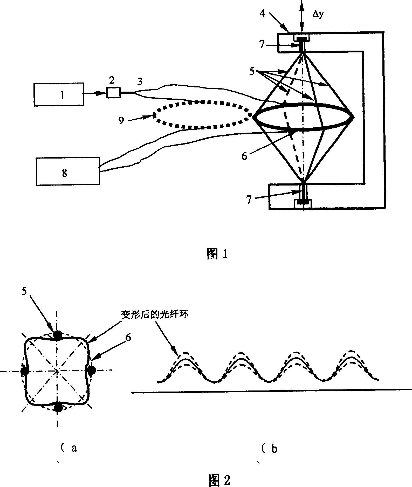
[0011] As shown in Figures 1 and 2, the present invention includes: a light source 1, an optical fiber coupler 2, a Y-shaped optical fiber 3, an overall deformation device 4, an optical fiber micro-bending deformation device 5, two optical fiber rings 6 and 9, and two pre-tightening bolts 7 and optical power meter 8 . The connection relationship is: the light emitted by the light source 1 enters the input end of the Y-shaped optical fiber 3 through the optical fiber coupler 2, and the optical fibers at the two output ends of the Y-shaped optical fiber 3 are made into two optical fiber rings 6, 9 with the same size and the same number of turns. One of the optical fiber rings 6 is installed in the optical fiber micro-bending deformation device 5, and the optical fiber micro-bending deformation device 5 and the optical fiber ring 6 are installed together in the overall deformation device 4 through two pre-tightening bolts 7, and the other optical fiber ring 9 is placed freely. Bo...


PUM


Abstract

An optical fiber micro bent displacement sensor, which contains light source, optical fiber coupler, Y type optical fiber, integral distortion device, optical micro bent distortion device, two optical rings, two pretension screw and optical power meter. Said invention adopts separated integral distortion device and optical fiber micro distortion device, can design the rigidity and strength of integral distortion according to need for adapting different frequency and amplitude signal measurement.

Description

technical field [0001] The invention relates to a sensor in the technical field of testing, in particular to an optical fiber microbending displacement sensor. Background technique [0002] There are various displacement meters and optical fiber sensors at home and abroad. The optical fiber micro-bend sensing displacement meter uses the slight displacement to cause the bending change of the optical fiber itself, resulting in the change of the power of light transmitted in the optical fiber to measure the displacement. [0003] After searching the literature of the prior art, it is found that the Chinese patent number is: 96116927.3, and the name is: "Optical Fiber Microbend Sensor". The principle of microbending loss reflects the displacement through the change of the loss of the transmitted light in the optical fiber caused by the change of the bending degree of the optical fiber, and realizes the detection of the strain. It can be used not only as a tensile and compressiv...

Claims


Application Information

Patent Timeline
Patent Type & Authority Patents(China)
IPC IPC(8): G01D5/353G01B11/02
Inventor 陈巨兵余征跃汪恒挥俞忠
Owner SHANGHAI JIAO TONG UNIV
Why Eureka
Try Eureka