Supercharge Your Innovation With Domain-Expert AI Agents!

Rotor type high sensitive water flowmeter

A rotary-wing water meter and rotary-wing technology are applied in measuring devices, instruments, volume measurement and other directions, which can solve the problems of increasing manufacturing difficulty, and achieve the effects of increasing casting and processing difficulty, low cost and avoiding economic losses.

Inactive Publication Date: 2008-01-09
柳吉君
View PDF6 Cites 0 Cited by
  • Summary
  • Abstract
  • Description
  • Claims
  • Application Information

AI Technical Summary

Problems solved by technology

However, in this technical solution, since the heavy iron is directly matched with the watch case, the watch case as a casting not only needs to be redesigned and cast, but also must ensure a certain precision in casting, which greatly increases the difficulty of manufacturing

Method used


Image

  • Rotor type high sensitive water flowmeter
  • Rotor type high sensitive water flowmeter

Examples


Embodiment Construction

[0019] The present invention will be further described in detail below in conjunction with the accompanying drawings and embodiments.

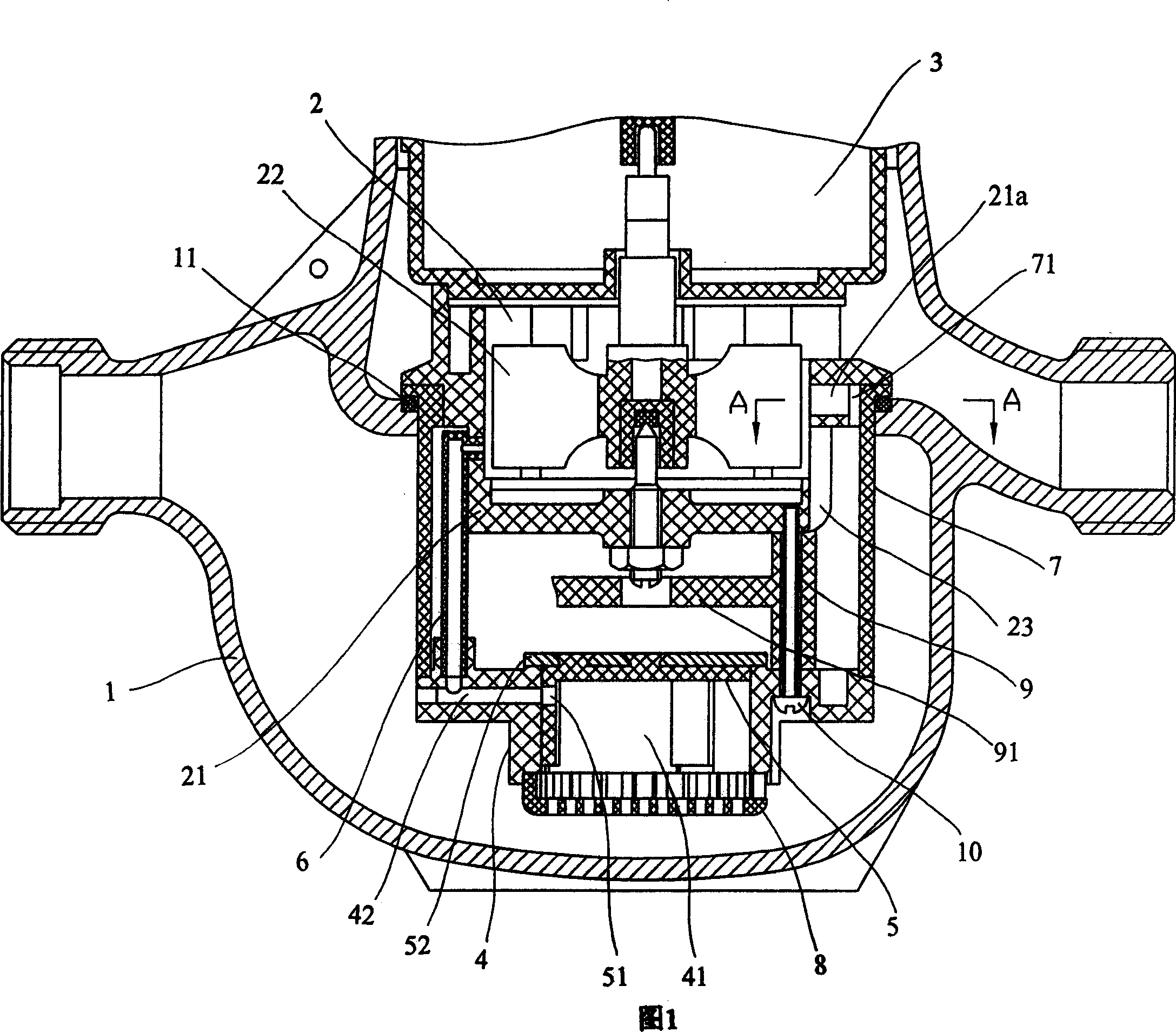
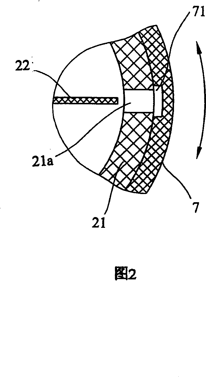
[0020] As shown in Figures 1 to 2, the rotor-type water meter includes a watch case 1, a rotor-type metering mechanism 2 and an indicating mechanism 3 arranged in the water flow channel inside it, wherein the indicating mechanism 3 is located on the metering mechanism 2 and is connected by transmission. The casing 21 of the metering mechanism 2 is provided with a rotor 22, and the lower part of the casing 21 is provided with a water inlet 23, and a flow diversion mechanism is also arranged under the metering mechanism 2, including:

[0021] A valve seat 4 has a water inlet hole 41 in its center and a small water hole 42 on its side wall, and a water filter screen cover 8 is also connected under the water inlet hole 41 of the valve seat 4;

[0022] A valve core 5 covers the water inlet hole 41 of the valve seat 4, and has a small hole 51 on the...


PUM


Abstract

Water meter includes case, rotary wing type metering mechanism, and indicating mechanism connected to the metering mechanism. There is a rotary wing inside case of the metering mechanism. A split flow mechanism setup inside the metering mechanism consists of following parts: valve seat including inlet opening and limber hole; valve core covering the inlet opening, and there is a small hole on side wall; one end of conduit connected to limber hole and another end conduit connected to a chamber, which is interconnected to place the rotary wing located; a split flow chamber is formed in lower part of case. The invented meter is able to make counting even in condition of trickling water so as to extend measuring range of water meter. The meter is easy to be manufactured.

Description

technical field [0001] The invention relates to a water meter, in particular to a rotor type water meter. Background technique [0002] Existing civil water meters are mainly rotor-type water meters, which generally include a watch case and a rotor-type metering mechanism and an indicating mechanism set in the inner water flow channel, wherein the indicating mechanism is located on the metering mechanism and is connected by transmission. The rotor has a water inlet hole in the lower part of the shell. In the working state, tap water flows in from the water inlet of the watch case at a certain flow rate, and then enters the metering mechanism, and the rotor blades impacting it rotate, and then drive the indicating mechanism to work and display the flow rate. , the water flowing out from the metering mechanism, and finally flows out from the water outlet of the watch case. The disadvantage of the water meter with this structure is that due to the certain frictional resistance...

Claims


Application Information

Patent Timeline
Patent Type & Authority Patents(China)
IPC IPC(8): G01F1/05G01F15/00
Inventor 柳吉君
Owner 柳吉君
Features
  • R&D
  • Intellectual Property
  • Life Sciences
  • Materials
  • Tech Scout
  • Unparalleled Data Quality
  • Higher Quality Content
  • 60% Fewer Hallucinations
Learn More