Electro-optical device, its driving circuit, driving method and electronic apparatus

A technology for driving circuits and electro-optical devices, which is applied to other seating furniture, passive exercise equipment, cathode ray tube indicators, etc., can solve the problems of halving the period and shortening the scanning period.

Inactive Publication Date: 2008-01-30
SEIKO EPSON CORP
View PDF4 Cites 0 Cited by
  • Summary
  • Abstract
  • Description
  • Claims
  • Application Information

AI Technical Summary

Problems solved by technology

[0007] However, in the above-mentioned technologies, although the display quality of moving images is improved by impulsive display, there is a disadvantage that high-speed writing is required.
The reason is that in the technology of setting a non-display field between a certain frame and the next frame, the period for scanning is shortened due to the period of the non-display field, and the black is written in the same period after the signal for display is written. In the level signal technology, since it is necessary to select the scanning line twice, the period for writing the display signal is halved.

Method used


Image

  • Electro-optical device, its driving circuit, driving method and electronic apparatus
  • Electro-optical device, its driving circuit, driving method and electronic apparatus
  • Electro-optical device, its driving circuit, driving method and electronic apparatus

Examples


Embodiment Construction

[0032] Hereinafter, modes for carrying out the present invention will be described with reference to the drawings.

[0033]

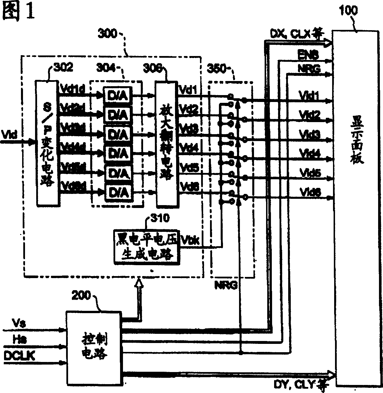
[0034] FIG. 1 is a block diagram showing the configuration of an electro-optical device according to a first embodiment of the present invention.

[0035] As shown in the figure, the electro-optical device is constituted by a display panel 100 , a control circuit 200 , a processing circuit 300 and a selector 350 . Among them, the control circuit 200 generates timing signals or clock signals for controlling each part according to the vertical scanning signal Vs, the horizontal scanning signal Hs, and the dot clock signal DCLK supplied from a not-shown host device.

[0036] The processing circuit 300 is composed of an S / P conversion circuit 302 , a D / A converter group 304 , an amplification and inversion circuit 306 , and a black level voltage generation circuit 310 .

[0037] Among them, the S / P conversion circuit 302 distributes the image data Vid to...


PUM


Abstract

To improve the display quality of a moving picture by performing a hold-type display of a liquid crystal, etc. using an impulse-type response. A selection voltage is applied to a selected scanning line during an effective horizontal scan period, and a voltage corresponding to the brightness of a pixel corresponding to an intersection with the selected scanning line is applied to one data line. During a horizontal flyback period when another scanning line is selected, a selection voltage is applied to the selected scanning line and a voltage allowing the pixel to display black as the least brightness is applied to the data line. As a result, the display of the pixel is erased and the data lines are precharged with the voltage erasing the display, for preparation of the subsequent writing operation.

Description

technical field [0001] The present invention relates to an electro-optic device suitable, for example, for the display of images with motion. A driving circuit for an electro-optical device, a driving method for an electro-optical device, and an electronic device. Background technique [0002] In recent years, electro-optic devices such as liquid crystals that display by electro-optic changes have been widely used in various electronic equipment or televisions as display devices that replace cathode ray tubes (CRTs) due to their advantages such as thinness, small size, and low power consumption. Apply it. [0003] Although this electro-optic device can be roughly classified into an active matrix type in which pixels are driven by switches and a cell-source matrix type in which pixels are driven without switching elements, if the electro-optic device is classified according to the driving method, etc., among them, the active matrix type based on the former In the type, sinc...

Claims


Application Information

Patent Timeline
Patent Type & Authority Patents(China)
IPC IPC(8): G09G3/36G09G3/20G02F1/133G09G5/10
CPCG09G3/3648G09G3/3688G09G3/3611G09G3/3677G09G2320/10G09G2310/0248A61H1/005A61H1/02A47C21/006A61H2201/0146A61H2201/1215
Inventor 青木透
Owner SEIKO EPSON CORP
Why Eureka
Try Eureka