Movable reed of electromagnetic relay

A technology of electromagnetic relays and relays, which is applied in the direction of electromagnetic relays, detailed information of electromagnetic relays, relays, etc., can solve the problems of many processing steps, low work efficiency, long assembly process, etc., and achieve the elimination of additional resistance and possible existing, improve Work efficiency and stability, save the effect of equipment investment

Active Publication Date: 2008-02-13
XIAMEN HONGFA SIGNAL ELECTRONICS CO LTD
View PDF7 Cites 0 Cited by
  • Summary
  • Abstract
  • Description
  • Claims
  • Application Information

AI Technical Summary

Problems solved by technology

In several electromagnetic relays disclosed in CN98806661.0, EP0727803, US5337029 and JP11-345555 invention patents, it is necessary to weld the moving reed and the moving spring lead-out pin of the relay together during final assembly. Such a moving spring lead-out method Not only there are hidden dangers of solder joints, but additional processing equipment is required, and the processing steps are many and complicated; the two kinds of electromagnetic relays disclosed in the invention patents of CN200310114279 and US6765462 have the advantage that the creepage distance from the armature to the moving spring is longer, The disadvantage is that the armature is required to drive the push block, and the push block drives the moving spring to work. The work efficiency is low, the assembly process is long, and the stability of the relay is poor.

Method used


Image

  • Movable reed of electromagnetic relay
  • Movable reed of electromagnetic relay
  • Movable reed of electromagnetic relay

Examples


Embodiment 1

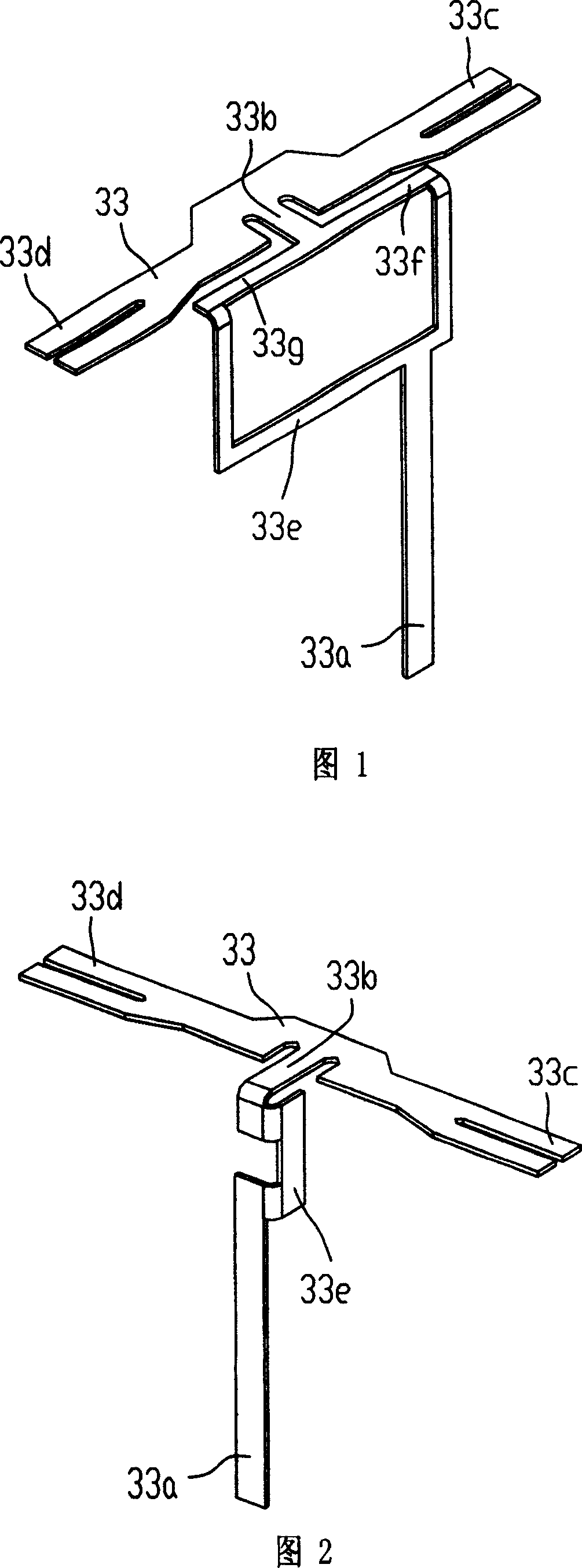
[0015] As shown in Figure 1, the moving spring 33 is an integrated design, including three free ends, one end is the moving spring lead-out pin 33a of the electromagnetic relay, and the other two ends are the contact ends 33c, 33d of the moving spring, and also include a connecting portion 33e, 33f, 33g and 33b; the two contact ends 33c, 33d of the moving spring 33 and the connecting parts 33e, 33f, 33g and 33b form an "I" shape structure; the connecting parts 33e, 33f, 33g and 33b of the moving spring 33 support the moving spring 33 , let the two contact ends 33c, 33d do a seesaw movement, and the connecting parts 33e, 33f, 33g and 33b are conductors, so that the relay load is directly transmitted from the contact end 33c or 33d to the moving spring lead-out pin 33a of the relay, eliminating Added resistance due to joining of several parts.

Embodiment 2

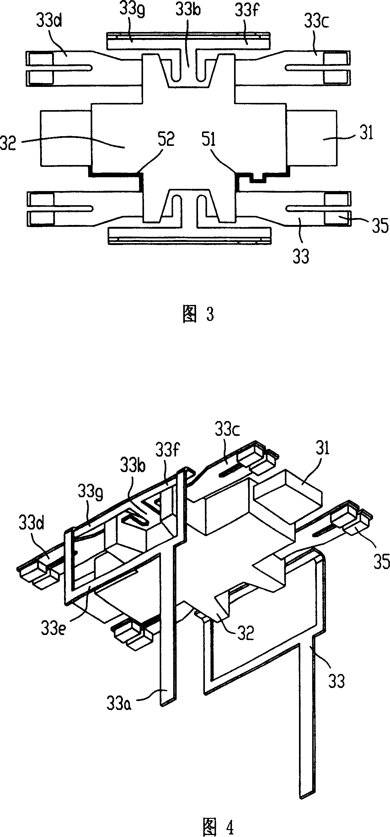
[0017] Fig. 2 has provided another embodiment of moving spring of the present invention, and this moving spring 33 is one body, comprises three free ends, and one end is the moving spring pin 33a of relay, and the other two ends are the contact end 33c of moving spring , 33d, also includes connecting parts 33e and 33b; the two contact ends 33c, 33d of the moving spring 33 and the connecting parts 33e and 33b form a "T" shaped structure. The connecting parts 33e and 33b of the moving spring 33 support the moving spring 33, allowing the two contact ends 33c and 33d to do a seesaw movement, and the connecting parts 33e and 33b are conductors, so that the relay load is directly transferred to the relay from the contact ends 33c or 33d The movable spring leads out pin end 33a, has eliminated the additional resistance that produces because of several parts joints.

Embodiment 3

[0019] As shown in Figures 1 and 2, the contact ends 33c, 33d of the moving spring 33 are "匚" shaped; the two contact ends 33c, 33d of the moving spring 33 are welded with contacts.


PUM


Abstract

Structure of improved movable reed of electromagnetic relay is as following: there are two contact pieces, one lead out piece and a junction piece in the relay; located in middle of the two contact pieces, the junction piece connects the two contact pieces; the two contact pieces include two free ends, and another free end is located at low end of the lead out piece; though the junction piece, the two contact pieces are connected to upper end of the lead out piece. Thus, contact ends of movable reed are integrated with the lead out piece. Advantages are: omitting procedure for welding contact piece and lead out piece etc; eliminating cold joint and additional resistance caused by jointed parts; keeping enough creepage distance, and raising stability of driving part, acceptability of products etc.

Description

technical field [0001] The invention relates to an electromagnetic relay, in particular to a moving spring of the electromagnetic relay. Background technique [0002] Electromagnetic relays are widely used in various automatic control equipment. Due to the needs of technological development, electromagnetic relays are required to have a more compact structure, smaller volume, longer service life and higher reliability without reducing the load. In several electromagnetic relays disclosed in CN98806661.0, EP0727803, US5337029 and JP11-345555 invention patents, it is necessary to weld the moving reed and the moving spring lead-out pin of the relay together during final assembly. Such a moving spring lead-out method Not only there are hidden dangers of solder joints, but additional processing equipment is required, and the processing steps are many and complicated; the two kinds of electromagnetic relays disclosed in the invention patents of CN200310114279 and US6765462 have th...

Claims


Application Information

Patent Timeline
Patent Type & Authority Patents(China)
IPC IPC(8): H01H50/54H01H50/58H01H50/14
Inventor 王俊青
Owner XIAMEN HONGFA SIGNAL ELECTRONICS CO LTD
Why Eureka
Try Eureka