Supercharge Your Innovation With Domain-Expert AI Agents!

Control of air conditioning cooling or heating coil

A technology of control components and headers, applied in heating methods, lighting and heating equipment, space heating and ventilation, etc., can solve the problems of time-consuming water side balance of cold water systems and affecting system performance, etc., to ensure load performance and controllability sex, guaranteed low effect

Inactive Publication Date: 2008-02-27
IOTACS TECH
View PDF7 Cites 0 Cited by
  • Summary
  • Abstract
  • Description
  • Claims
  • Application Information

AI Technical Summary

Problems solved by technology

Achieving waterside balancing of chilled water systems is time consuming and can impact system performance if not performed accurately

Method used


Image

  • Control of air conditioning cooling or heating coil
  • Control of air conditioning cooling or heating coil
  • Control of air conditioning cooling or heating coil

Examples


Embodiment Construction

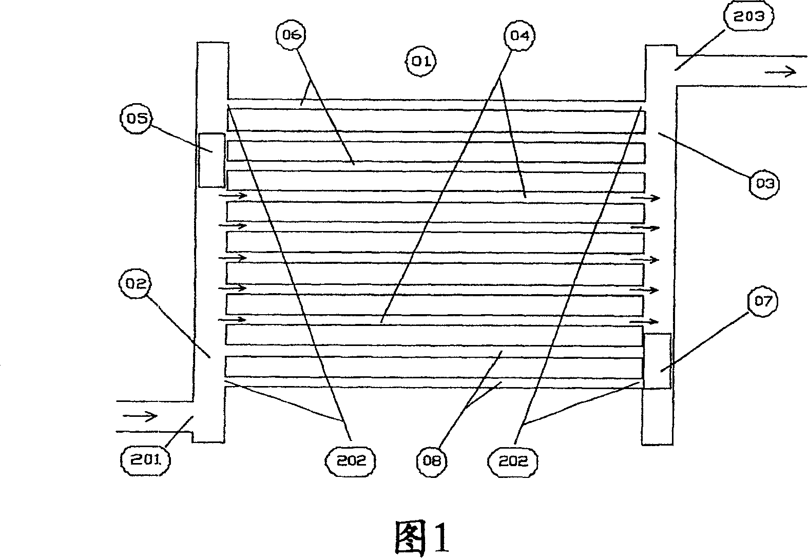
[0060] Referring to Figure 1, the cold water coil 1 has a supply header 2, a return header 3, and an interconnecting circuit 4 between the supply header and the return header. The plurality of interconnecting circuits 4 are connected to the respective headers 2 and 3 through a plurality of corresponding connection ports 202 . The plurality of connection ports 202 are located at different positions and are arranged in a top-to-bottom row along the headers 2 and 3 . Row. The fluid flows into the supply header 2 through the supply port 201 at the bottom end of the header 2 , and flows from the return header 3 through the return port 203 at the top end of the return header 3 . The sliding piston 5 is located in the supply header 2 and is equipped with a watertight seal to prevent the flow of water from the lower part of the supply header 2 to the upper part. In this figure, the piston 5 cuts off the water flow to the upper three circuits 6, the coil surface temperature in the are...


PUM


Abstract

A fluid heat exchange device, comprising a header and a plurality of interconnecting circuits between an supply port and a return port, the interconnecting circuits being connected to the header by a corresponding plurality of connection ports at different locations along the header wherein the header includes a blocking control element inside the header, the blocking control element being positionally adjustable along the header to selectively block fluid flow from the supply port through the connection ports of the plurality of interconnecting circuits, thereby selectively controlling those interconnecting circuits of the plurality of interconnecting circuits which are subjected to fluid flow therethrough in dependency on the position of the blocking control element.

Description

technical field [0001] The present invention relates to an improvement in the control of a fluid heat exchange device, particularly a cooling (cooling) water cooling coil for air conditioning (processing) equipment and part load capacity control of fan coil units for comfort cooling and industrial applications . In the description below, the device is used for cooling applications, but the device can also be used for heating applications. Background technique [0002] When a conventional throttle-controlled cooling coil is used at part load, its latent heat capacity drops much faster than its sensible heat capacity, which increases the relative humidity of the space and reduces comfort. From a latent heat removal standpoint, sensible heat sources upstream of the cooling coil rather than in the conditioned space contribute no effective sensible heat load. The coils need to be selected with a high waterside pressure drop at full load to ensure turbulence in the circuit at pa...

Claims


Application Information

Patent Timeline
Patent Type & Authority Patents(China)
IPC IPC(8): F24F11/06F28F27/02F28F9/26F28D1/053F28F27/00
CPCF24F11/06F28D1/05316F28F27/02F28F27/00F24F11/83F24F11/85F24F11/84F28F9/26
Inventor G·S·维采瑙
Owner IOTACS TECH
Features
  • R&D
  • Intellectual Property
  • Life Sciences
  • Materials
  • Tech Scout
  • Unparalleled Data Quality
  • Higher Quality Content
  • 60% Fewer Hallucinations
Learn More