Hydraulic system for damping the motion of rotation of a swivel joint between two vehicle parts of an articulated vehicle, of an articulated bus for example

a technology of hydraulic system and swivel joint, which is applied in the direction of brake system, vehicle, towing device, etc., can solve the problems of hydraulic system particularly failing to work, hardly controllable vehicles, and increased oscillations of vehicles, so as to ensure the controllability of vehicles

Inactive Publication Date: 2002-07-23
HUBNER GUMMI UND KUNST
View PDF11 Cites 20 Cited by
  • Summary
  • Abstract
  • Description
  • Claims
  • Application Information

AI Technical Summary

Benefits of technology

is therefor to develop a hydraulic system of the type mentioned above that guarantees the controllability of the vehicle even in case the electric installation of a vehicle and with

Problems solved by technology

Such a damping of the motion of rotation of the two joint members relative to one another is absolutely necessary, since otherwise the vehicle is hardly controllable.
In this case, the osc

Method used


Image

  • Hydraulic system for damping the motion of rotation of a swivel joint between two vehicle parts of an articulated vehicle, of an articulated bus for example
  • Hydraulic system for damping the motion of rotation of a swivel joint between two vehicle parts of an articulated vehicle, of an articulated bus for example
  • Hydraulic system for damping the motion of rotation of a swivel joint between two vehicle parts of an articulated vehicle, of an articulated bus for example

Examples


Embodiment Construction

FIGS. 5 and 6 show a swivel joint referred to with reference number 1 and provided with two joint members 10, 20 which are pivotably connected together at the buckling point 30, by a pin for example. The joint member 20 may hereby be linked directly to the vehicle which is hinted at with reference number 21, whereas the joint member 10 is pivotably connected to the vehicle 11 by a horizontal running axle, if need be by an intermediate link. Such a connection is necessary in order to allow the nodding movements of the two vehicles 11, 21 relative to one another.

The subject matter of the invention is henceforth the connection, in fact the connection in series or the parallel connection of the proportional pressure control valve to the mechanical pressure control valve.

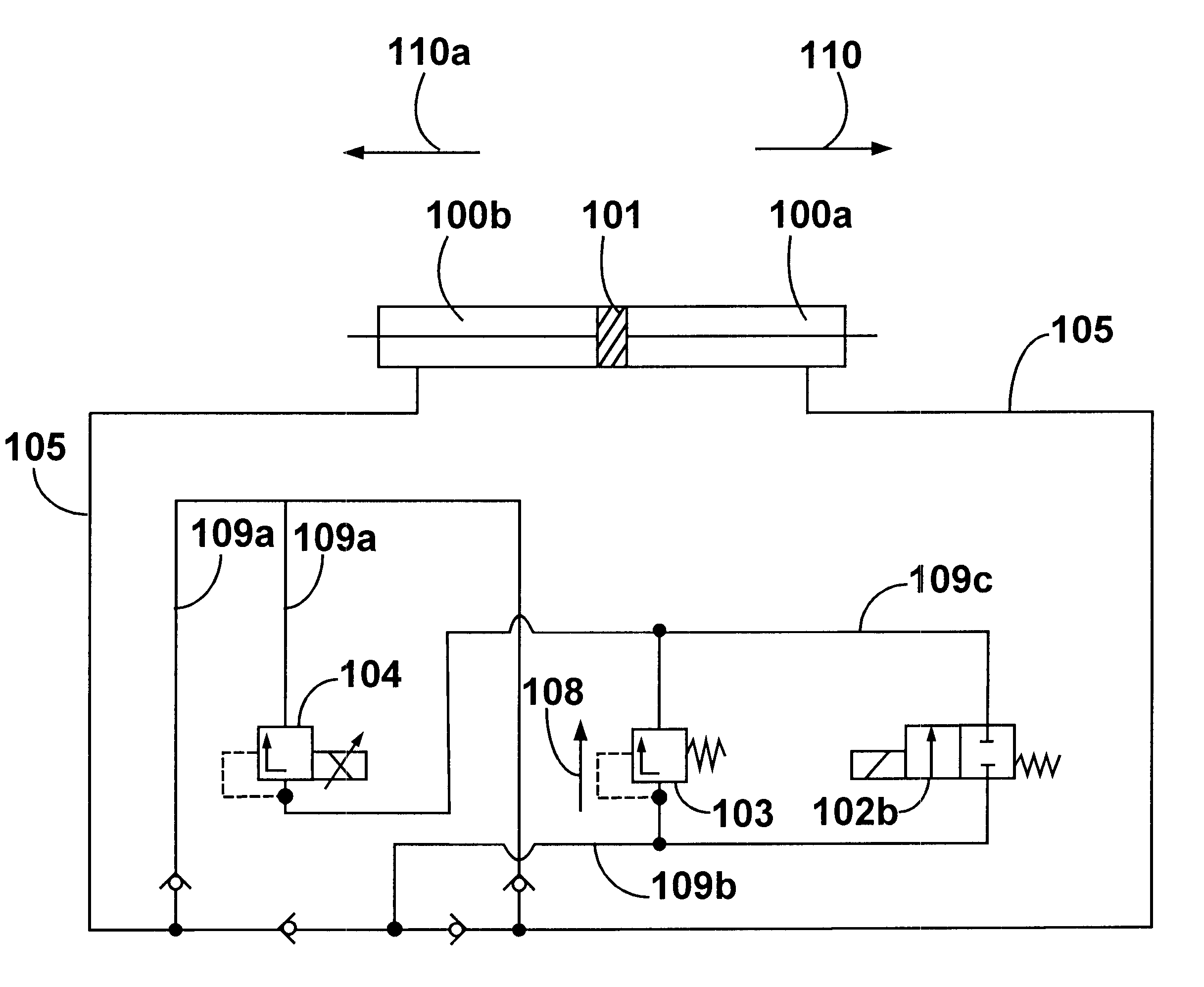
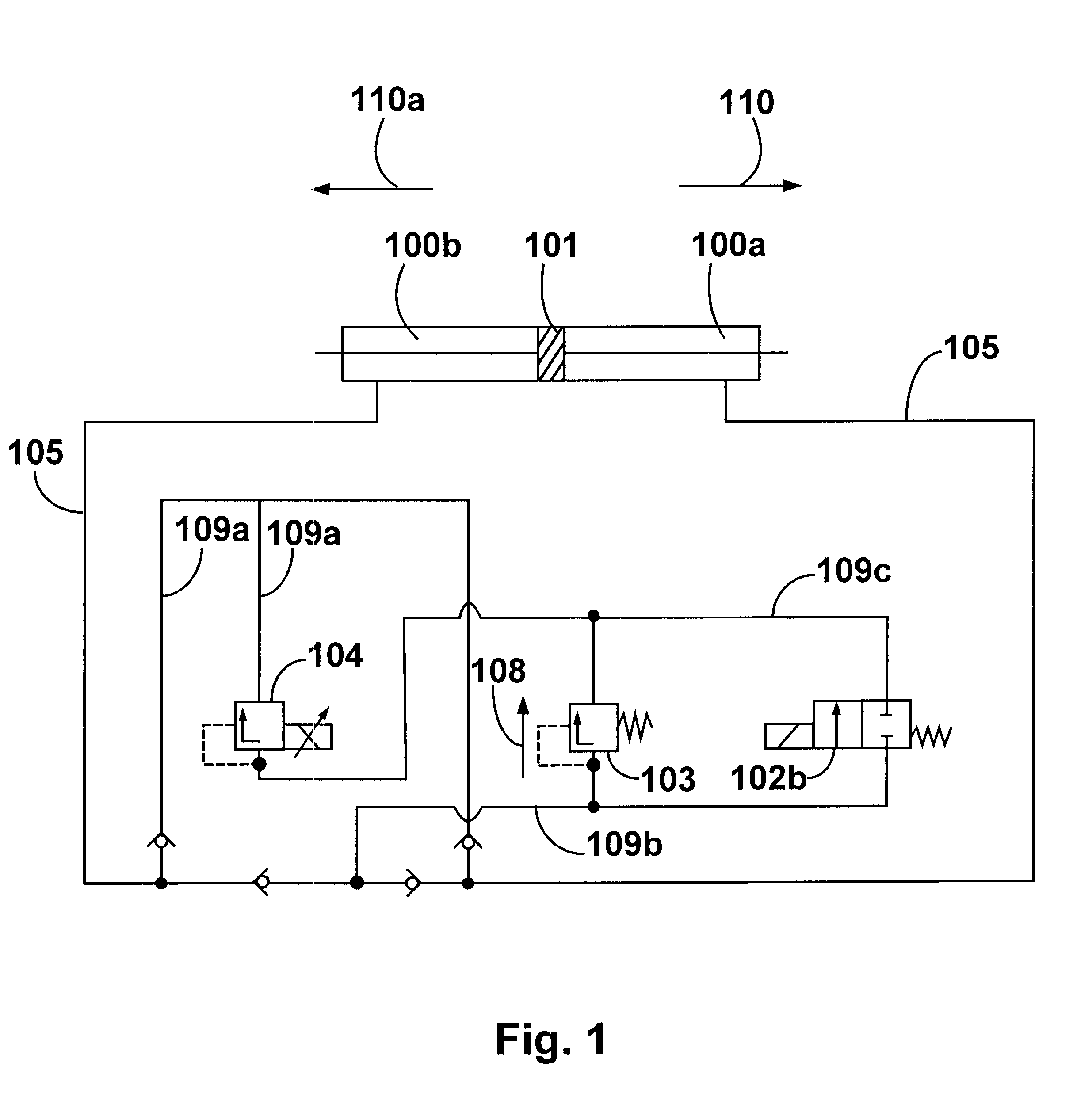
As may be seen in FIG. 1, a connection in series is made with a double-acting cylinder. The cylinder, which is referred to as a whole with numeral 100, has two chambers 100a, 100b and communicates with the piston 101, wi...


PUM


Abstract

A hydraulic system for damping the motion of rotation of a swivel joint between two vehicle parts of an articulated vehicle, of an articulated bus for example, comprising a hydraulic damping device as well as an electrically triggerable proportional pressure control valve, whereas the proportional pressure control valve is arranged between the force side and the suction side of the damping device, a mechanical pressure control valve (103) being provided in addition to the proportional pressure control valve (104) in the conduit between the suction side and the force side of the damping device, and whereas a multiple-way valve is provided for the alternative drive of the pressure control valve (103) or of the proportional pressure control valve (104).

Description

CROSS-REFERENCE TO RELATED APPLICATIONS1. Field of the InventionThis application claims priority from German Patent Application No. 298 22 472.0 filed Dec. 18, 1998.2. Description of the Prior ArtA swivel joint as described above is well-known in the art. The prior art swivel joint comprises two joint members which may be pivotably connected to one another by an axle. The one joint member may hereby be linked directly to the one vehicle or vehicle part, whereas the other joint member may be connected to the vehicle or the vehicle part either directly by being pivotable around a horizontal running axle or indirectly via an intermediate link. Thanks to this axle, allowance is made for the fact that the swivel joint has to be able to yield to the nodding movements of the two vehicles relative to one another. According to a first embodiment, these swivel joints are provided on either side of the longitudinal axis of the vehicle or of the swivel joint with one hydraulic cylinder, whereas...

Claims


Application Information

Patent Timeline
IPC IPC(8): B62D47/00B62D53/00B62D47/02B62D53/08F16F9/512
CPCB62D47/025B62D53/00
Inventor BITTROFF, UWEKLOPPMANN, SVENSCHMELZER, HANS-UWEKLUTTERMANN, STEPHAN
Owner HUBNER GUMMI UND KUNST
Why Eureka
Try Eureka