Surface texture measuring instrument and calibration method thereof

A technology of surface characteristics and correction method, which is applied in the direction of measuring device, mechanical measuring device, mechanical counter/curvature measurement, etc., can solve the problem that more precise correction cannot be performed, and achieve the effect of precise correction

Inactive Publication Date: 2008-02-27
MITUTOYO CORP
View PDF4 Cites 23 Cited by
  • Summary
  • Abstract
  • Description
  • Claims
  • Application Information

AI Technical Summary

Problems solved by technology

However, in this reference 3, since the parameters to be corrected are lim

Method used


Image

  • Surface texture measuring instrument and calibration method thereof
  • Surface texture measuring instrument and calibration method thereof
  • Surface texture measuring instrument and calibration method thereof

Examples


no. 1 Embodiment approach

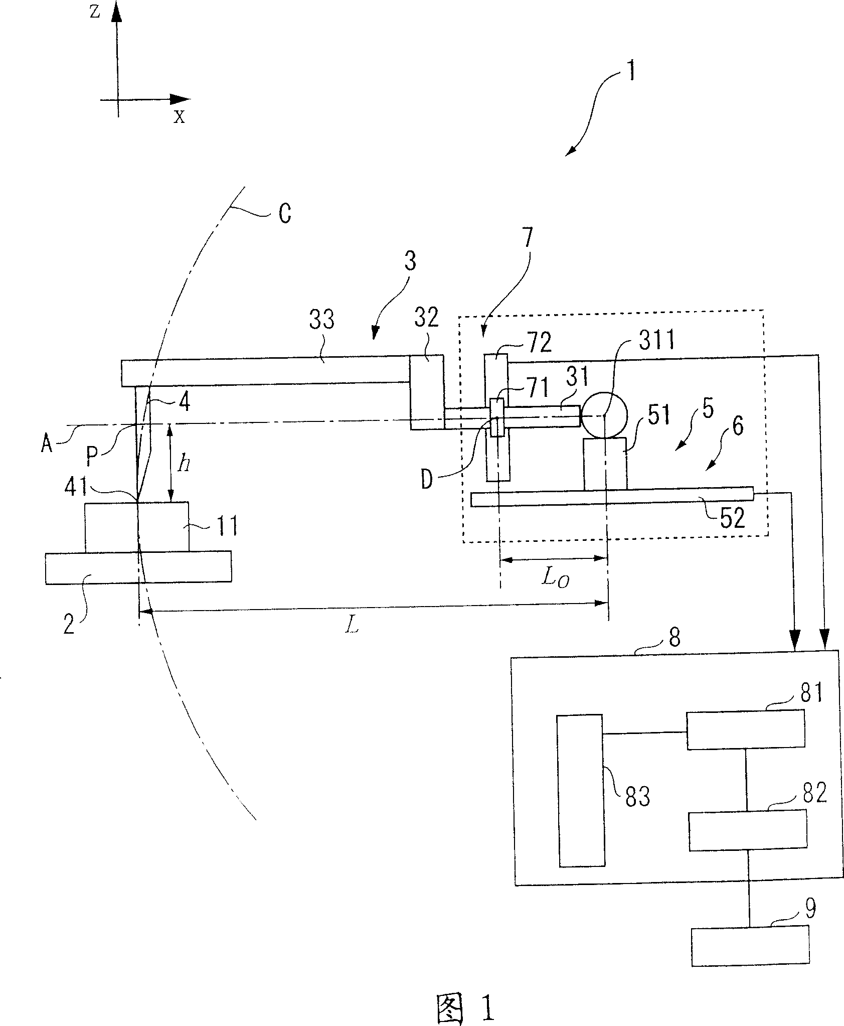
[0070] Next, a method of calibrating the surface characteristic measuring machine 1 of the present invention will be described.

[0071] The calibration method of the surface characteristic measuring machine 1 includes a measurement process, a substitution process, and a calibration process; the measurement process measures a calibration gauge 10 that includes a part of a substantially perfect circle in the cross-sectional shape; The detection result of detection device 6 and above-mentioned the 2nd detection device 7 is substituted into the evaluation formula based on the formula of circle, and the formula of this circle assumes that the central coordinate of perfect circle is (x c ,z c ), the radius is r; this correction process applies the least squares method to the evaluation formula obtained by the substitution process, and corrects each parameter included in the offset.

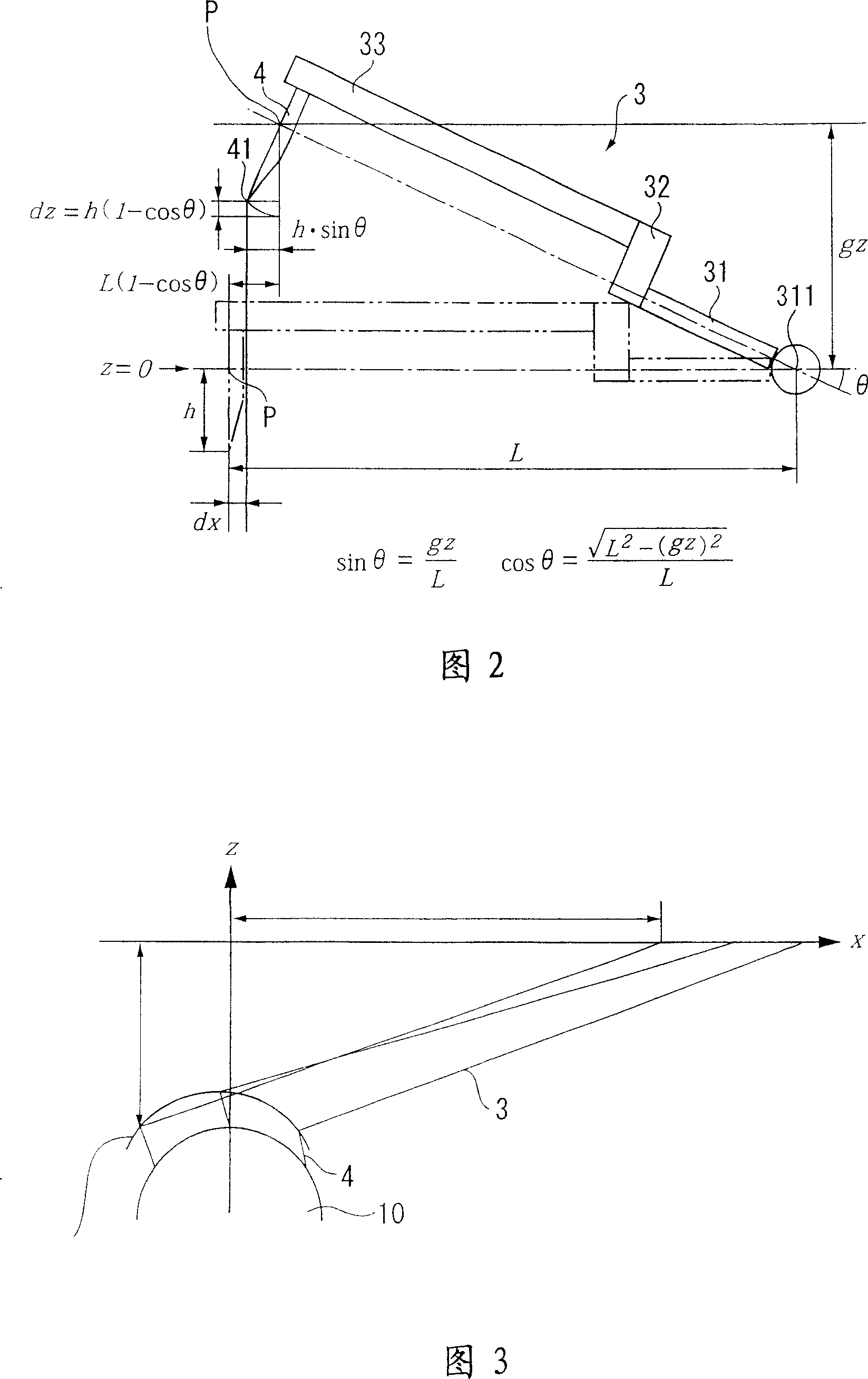
[0072] In the measurement process, as shown in FIG. 3 , the calibration gauge 10 which can be rega...

no. 2 Embodiment approach

[0094] Next, a second embodiment of the present invention will be described. The basic configuration of the second embodiment is the same as that of the first embodiment, but the second embodiment is characterized in that the least squares method is applied to the arm reference length L as a calibration target in addition to the calibration target of the first embodiment.

[0095] That is, the following least square calculation is performed with respect to the evaluation formula of formula (8).

[0096] Σ ( ∂ fi ∂ x C ) 2 Σ ...

no. 3 Embodiment approach

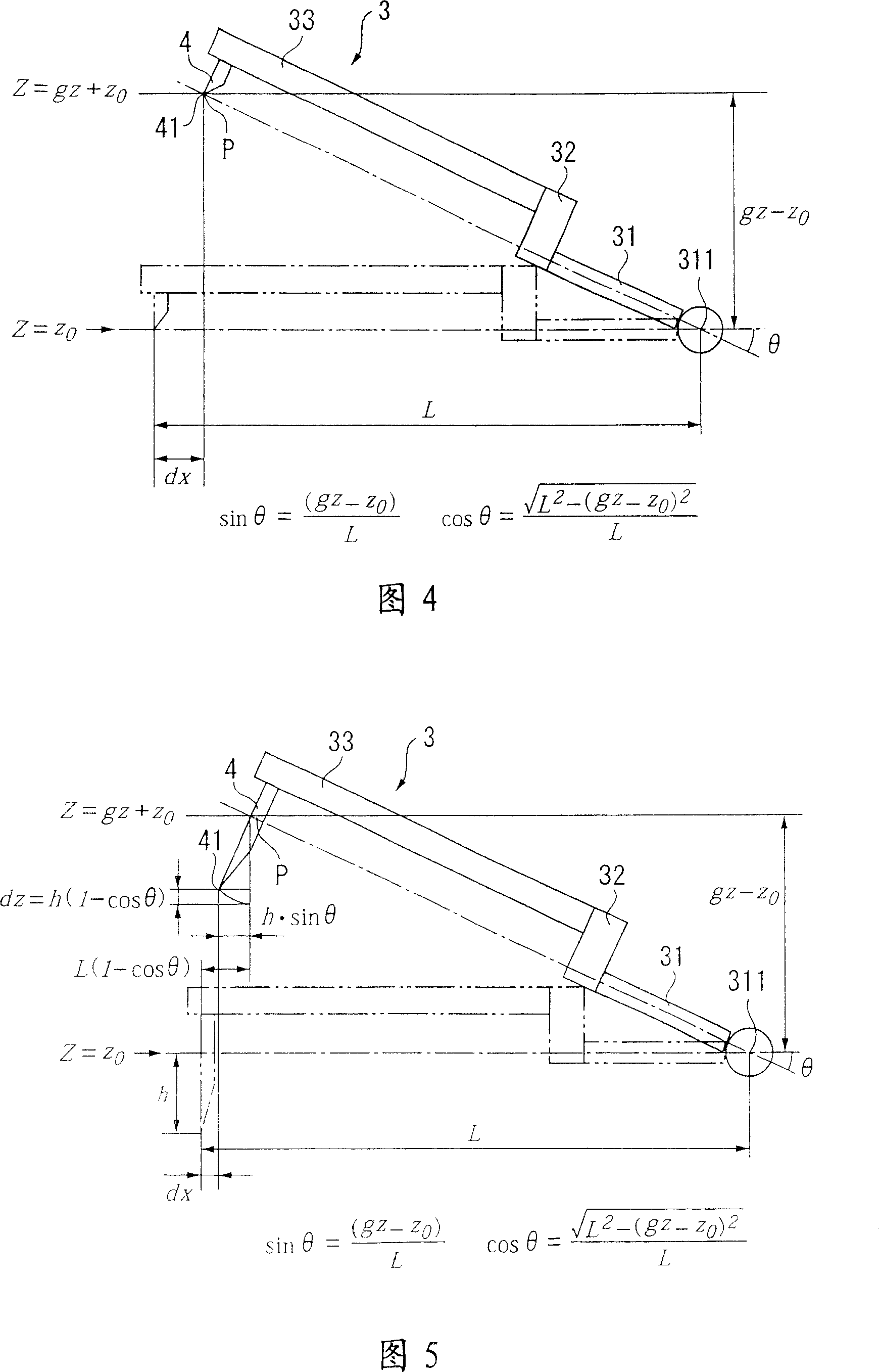
[0100] Next, a third embodiment of the present invention will be described. The basic configuration of the third embodiment is the same as that of the first embodiment, but the third embodiment is characterized in that the arm reference length L and the zero offset z0 are also the calibration targets in addition to the calibration targets of the first embodiment.

[0101] In the surface characteristic measuring machine 1 according to the third embodiment, as shown in FIG. 4 , the measurement contactor 41 is installed so as to substantially coincide with the reference point. That is, the front end correction amount h is substantially zero, and expressions corresponding to Expressions (5) and (6) as the amount of deviation caused by the swing of the arm 3 are expressed as the following expressions. When calculating the offset in the x direction, the zeroing offset of the second detection device is taken into consideration.

[0102] Wherein, the zeroing offset z0 is the z coordi...


PUM


Abstract

In a calibration method for a surface texture measuring instrument which measures the surface of a workpiece and includes an arm that is supported to be swingable around a base point thereof and is provided with a contact point at an end for scanning the workpiece surface, the calibration method includes a measurement step for measuring a calibration gauge the cross section of which contains a part of a substantially perfect circle, an assignment step for assigning the detection results from the measurement step in an evaluation formula based on the equation of a circle in which the center coordinates of the calibration gauge are (xc, zc) and the radius is 'r', and a calibration step for calibrating each parameter based on the results obtained in the assignment step.

Description

technical field [0001] The invention relates to a calibration method of a surface characteristic measuring machine, a calibration program of the surface characteristic measuring machine, a recording medium for recording the calibration program, and a surface characteristic measuring machine. Background technique [0002] In the past, surface property measuring machines for measuring surface properties such as surface roughness, waviness, contour shape, roundness, and straightness of an object to be measured are known. [0003] As shown in FIG. 1 , the surface characteristic measuring machine 1 has an arm 3 that swingably supports a base end 311 , a measuring contact 41 that is provided at the other end of the arm 3 and scans an object to be measured, and a detection arm 3 . A first detecting device 6 for displacement in the x direction, and a second detecting device 7 for detecting the swing of the arm 3 as a displacement in the z direction. [0004] Among them, the first d...

Claims


Application Information

Patent Timeline
IPC IPC(8): G01B5/00G01B21/30G01B5/008G01B5/012G01B5/20G01B5/28G01B21/00G01B21/04G01B21/20G01J1/10G05B19/401
CPCG01B5/28G01B5/20
Inventor 竹村勇
Owner MITUTOYO CORP
Why Eureka
Try Eureka