Outside stator for planar motor

A planar motor and stator technology, applied in the direction of electrical components, electromechanical devices, electric components, etc., can solve the problems of magnetic core 11b deformation, gap reduction, motor reliability and efficiency reduction, etc., to reduce deformation, reduce pressure, increase The effect of a large contact area

Inactive Publication Date: 2008-03-19
LG ELECTRONICS (TIANJIN) APPLIANCES CO LTD
View PDF6 Cites 0 Cited by
  • Summary
  • Abstract
  • Description
  • Claims
  • Application Information

AI Technical Summary

Problems solved by technology

However, as shown in FIG. 3, this prior art planar motor has a problem that part of the magnetic core 11b may be deformed due to the injection pressure generated when the molding material is injected or the shrinkage force generated when the molding material is hardened. Therefore, it is pressed into the center direction of the outer stator 11, so that the gap between the outer stator 11 and the inner stator 12 becomes smaller, resulting in conflict between the stator 10 and the rotor 20, which reduces the reliability and efficiency of the motor.

Method used


Image

  • Outside stator for planar motor
  • Outside stator for planar motor
  • Outside stator for planar motor

Examples


Embodiment Construction

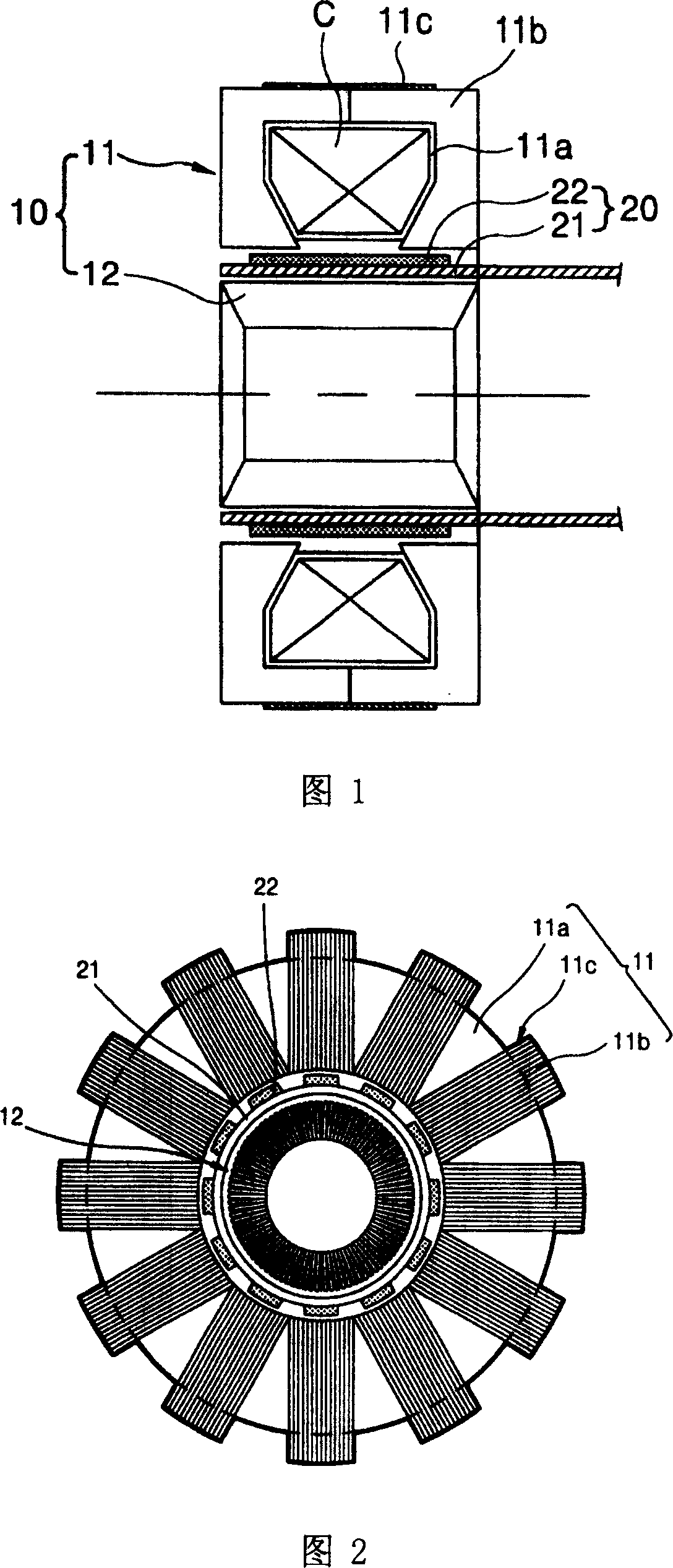
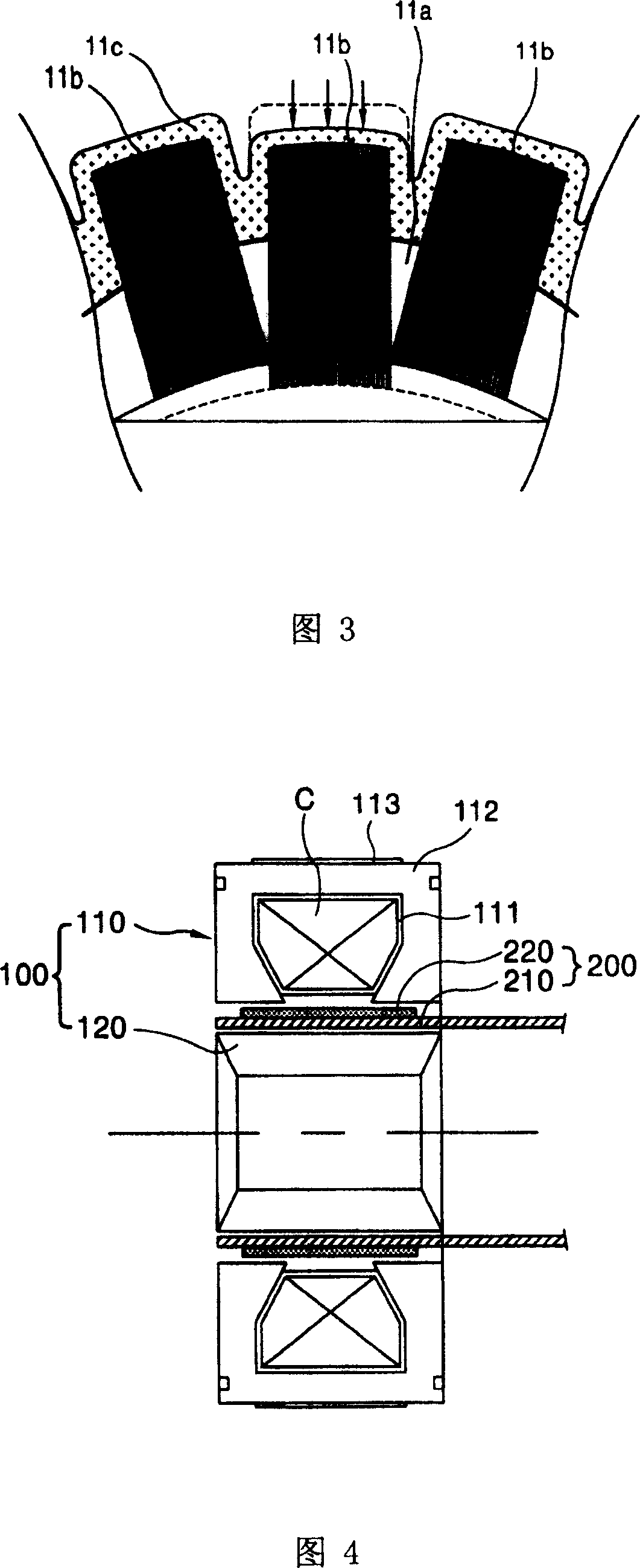
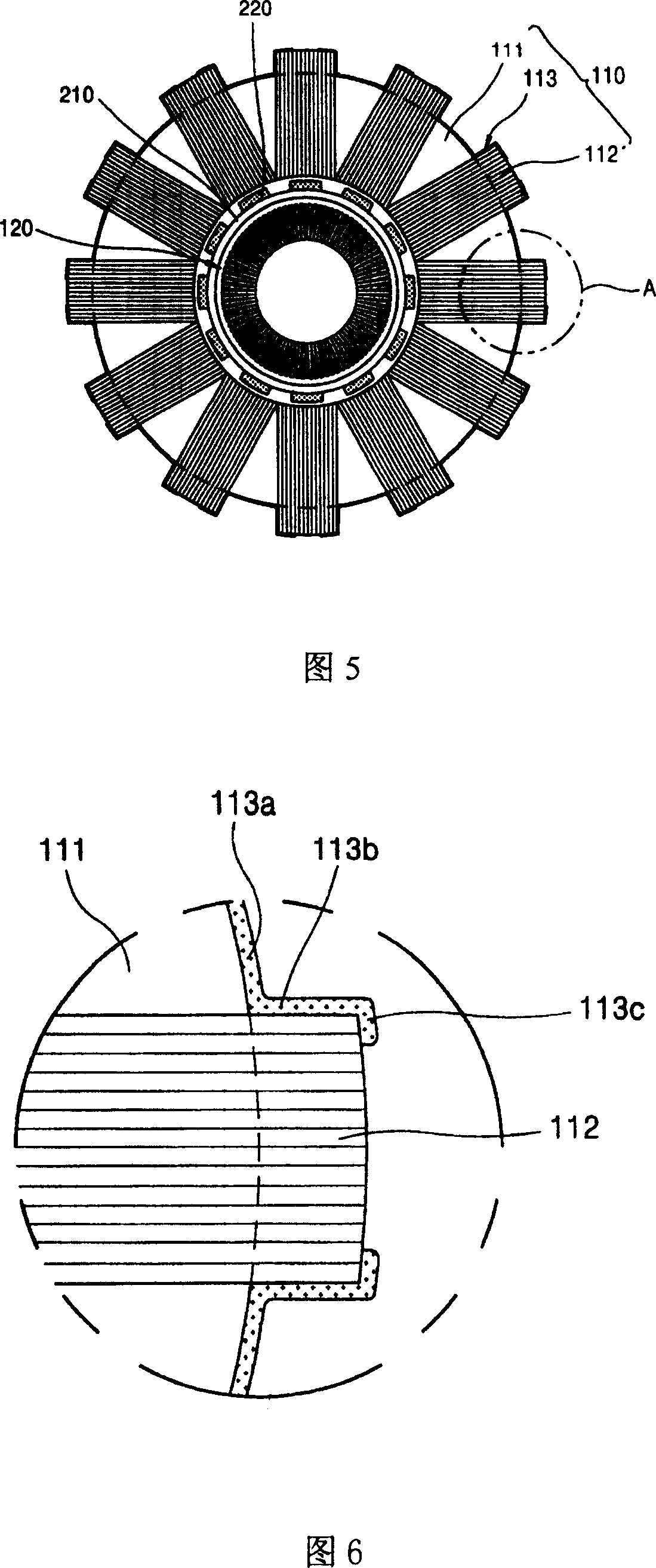
[0013] As shown in FIGS. 4 to 9 , the planar motor provided by the present invention is composed of a stator assembly 100 and a rotor assembly 200 . Wherein, the stator assembly 100 is composed of an outer stator 110 and an inner stator 120 . The outer stator 110 is fixed on the frame. There is a certain gap between the inner stator 120 disposed inside the outer stator 110 and the outer stator 110 . The rotor assembly 200 is disposed in the gap between the outer stator 110 and the inner stator 120, and it can perform linear reciprocating motion. The outer stator 110 is composed of a winding body 111 , a magnetic core 112 and a molded body 113 . The coil C may be embedded in the winding body 111 . The magnetic core 112 is formed by stacking a plurality of stator magnetic chips, which are combined on the outside of the winding body 111 . The molding body 113 can be fixed on the winding body 111 after the connecting portion of the magnetic core 112 is molded. The winding bod...


PUM


Abstract

The disclosed lateral stator is composed of wire winding body, magnetic core and molding body. The molding body comprises first, second, and third molding parts. First molding part is integrated on outer circumference face of the wire winding body. Second molding part formed with first molding part continuously is integrated on two side faces of interconnecting piece of magnetic core. Third molding part formed with second molding part continuously is integrated on partial outer circumference face. Tail end of molding part is made in shape of zigzag or triangle. The invention increases contact area of magnetic core, reduces press on magnetic core, reduces distortion of magnetic core and wire winding body farthest caused by molding press and shrink force. Thus, gap between outer stator and inner stator is kept constant.

Description

technical field [0001] The present invention relates to a planar motor, in particular to a planar motor capable of preventing the winding body or the magnetic core from being deformed when the surface molding is carried out on the winding body and the magnetic core arranged radially on the outer circumference of the winding body the outer stator. Background technique [0002] Generally, a planar motor is a motor that can change the three-dimensional structure magnetic field of a three-dimensional motor into a planar magnetic field, place a planar rotor assembly above a planar stator assembly, and make the rotor assembly move linearly under the change of the magnetic field. In this planar motor, the stator assembly consists of a cylindrical outer stator and an inner stator with a certain gap between the outer stator and the inner stator. The rotor assembly is installed between the outer stator and the inner stator, which can move back and forth. A coil may be installed on o...

Claims


Application Information

Patent Timeline
Patent Type & Authority Patents(China)
IPC IPC(8): H02K1/12H02K3/00H02K3/04
Inventor 宋雨宪
Owner LG ELECTRONICS (TIANJIN) APPLIANCES CO LTD
Why Eureka
Try Eureka