Seal device

A sealing device and sealing lip technology, which is applied in the direction of engine sealing, engine components, mechanical equipment, etc., can solve the problems of reduced sealing capacity of the sealing device, increased wear, and decreased sealing capacity, so as to prevent the decrease of sealing capacity and reduce sliding resistance , the effect of preventing sliding wear

Inactive Publication Date: 2008-04-09
EAGLE INDS
View PDF9 Cites 0 Cited by
  • Summary
  • Abstract
  • Description
  • Claims
  • Application Information

AI Technical Summary

Problems solved by technology

The seal lip 102a of the elastomer lip 102 and the seal lip 104a of the resin lip 104 are heated and softened, especially the wear of the seal lip 102a made of rubber material is aggravated, and the sealing ability is reduced.
[0013] When the sealing lip 102a of the elastomer lip 102 and the sealing lip 104a of the resin lip 104 are worn, the wear powder adheres between the sliding surfaces of the sealing lips 102a, 104a, reducing the sealing ability.
[0014] The seal lip 102a of the elastomer lip 102 and the seal lip 104a of the resin lip 104 are pressed against the rotation shaft 120 and rotated, so the normal rotation shaft 120 wears out quickly.
On the other hand, the rotating shaft 120, which is an equipment part, is expensive, and it cannot be easily replaced because it is assembled in the device.
Therefore, the sealing surfaces of the sealing lip 102a of the elastomer lip 102 and the sealing lip 104a of the resin lip 104 slide against the rotating shaft being worn, so the wear of these two sliding surfaces is increased, and the sealing ability of the sealing device is reduced.

Method used


Image

  • Seal device
  • Seal device
  • Seal device

Examples


Embodiment Construction

[0043] Hereinafter, a sealing device according to a preferred embodiment of the present invention will be described in detail with reference to the accompanying drawings. Each drawing described below is made according to the design drawing.

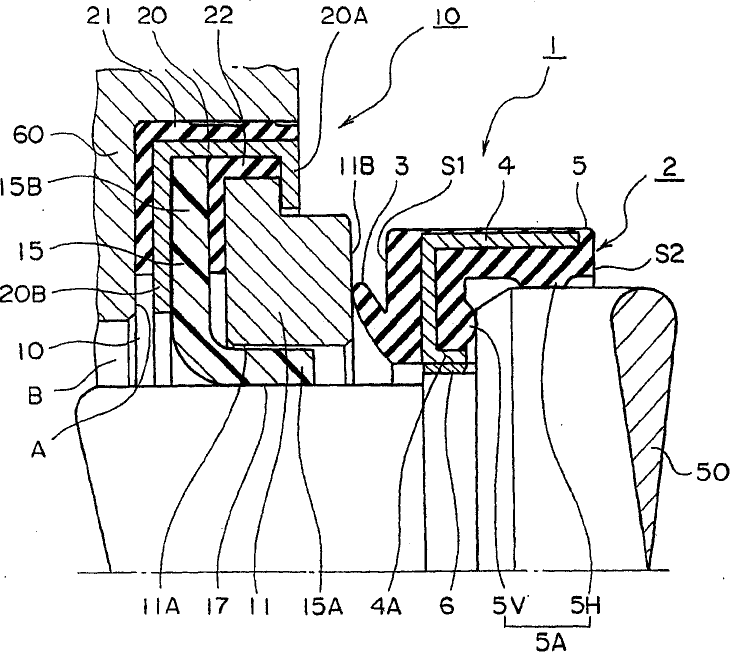
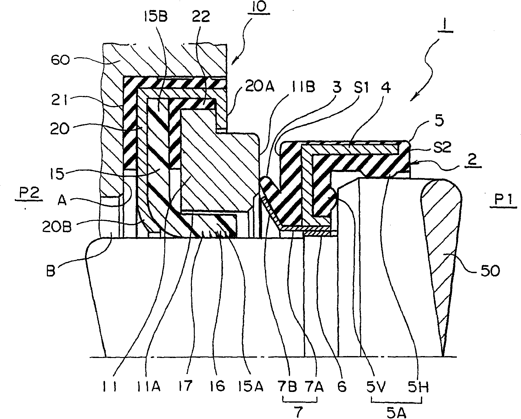
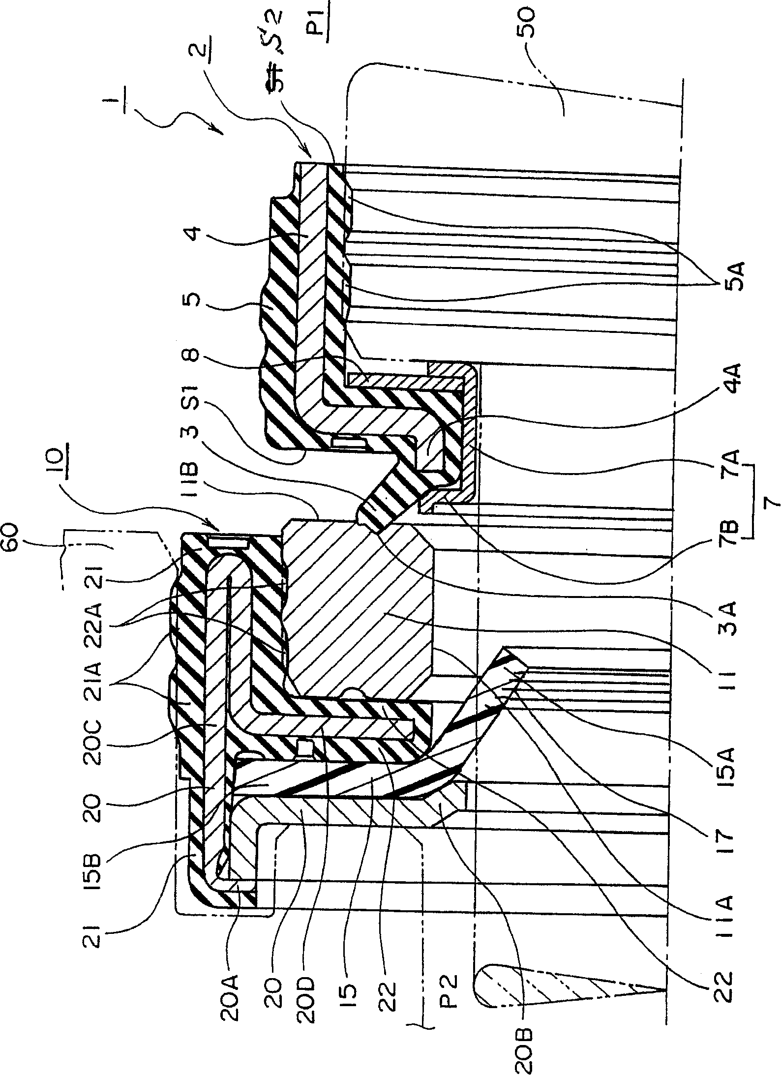
[0044] figure 1 It is a half cross-sectional view showing a sealing device 1 according to a preferred embodiment of the present invention.

[0045] figure 1 Among them, the sealing device 1 is formed by combining the end face seal 2 and the sealing part 10 to form a pair. In the seal portion 10, the seal ring 11 and the seal lip 15 are main constituent members.

[0046] The cross-section of the end face seal 2 is L-shaped, forming an end face seal body 5 . A protruding lip 3 extending outward in a V-shaped cross section is formed at one end of the end face sealing body 5 . In addition, the inner peripheral surface and the side surface of the end sealing body 5 are formed with a peripheral surface seal portion 5H and a side surface ...


PUM


Abstract

A seal device, wherein the contact part of a seal lip (15) with a magnetic part is separated from the contact part of an end face seal (2) with the magnetic part to prevent a material from being softened by the transfer of sliding heating from the seal lip (15) to the end face seal (2) so as to increase a seal performance, a projected lip (3) is extended aslant in outer radial direction and fitted to the seal face (11B) of a sealed ring (11), and a seal contact surface (17) is effectively fitted to a rotating shaft (50) so that the lip part (15A) of the seal lip (15) can seal sealed fluid on the inner peripheral surface (11A) side of the sealed ring (11).

Description

technical field [0001] The present invention relates to a sealing device that combines a sealing part and an end face seal into a pair, and performs sealing with separate opposing sealing surfaces. In particular, it relates to a sealing device for sealing a sealed fluid of various rotating equipment using a high pressure or a sealed fluid randomly changing between high pressure and low pressure. Background technique [0002] As a related art of the present invention, there are Figure 5 The shaft sealing device 100 is shown. [0003] Figure 5 The housing 101 of the shown shaft sealing device 100 is in sealing engagement with the inner peripheral surface of the housing 110 by means of an O-ring 106 . An elastic lip 102 and a reinforcement ring 103 supporting the back surface of the elastic lip 102 are disposed on the inner periphery of the housing 101 . [0004] Further, on the back surface of the reinforcement ring 103 opposite to the sealed fluid side, a resin lip 104 an...

Claims


Application Information

Patent Timeline
Patent Type & Authority Patents(China)
IPC IPC(8): F16J15/32F16J15/3268F16J15/34
CPCF16J15/324F16J15/3228F16J15/3456F16J15/32
Inventor 松井伸悟泷个平宜昭
Owner EAGLE INDS
Why Eureka
Try Eureka