
Adjustable camera sliding rail

An adjustable and sliding rail technology, which is applied in the direction of supporting machines, mechanical equipment, machine tables/supports, etc., can solve problems such as wear and harsh sound, and achieve the effect of avoiding sliding wear and adjusting the tightness

Pending Publication Date: 2021-09-21
候胖
View PDF10 Cites 0 Cited by
  • Summary
  • Abstract
  • Description
  • Claims
  • Application Information

AI Technical Summary

Problems solved by technology

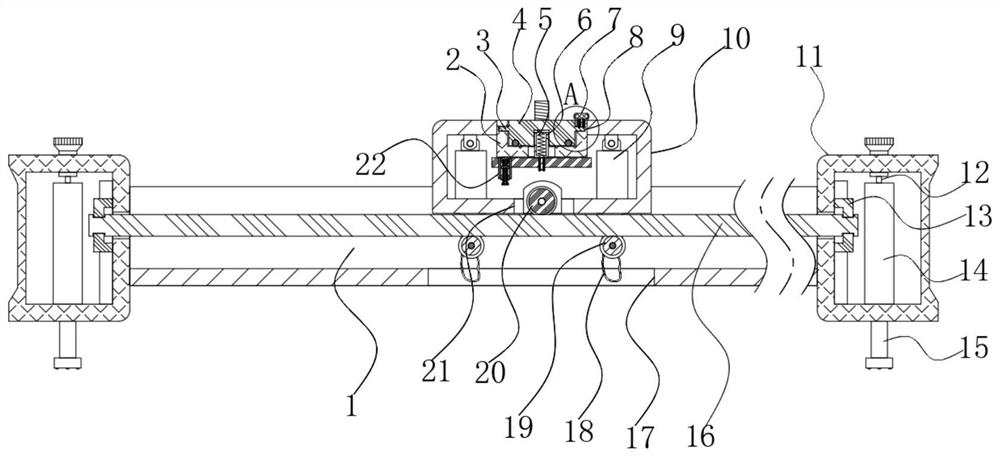
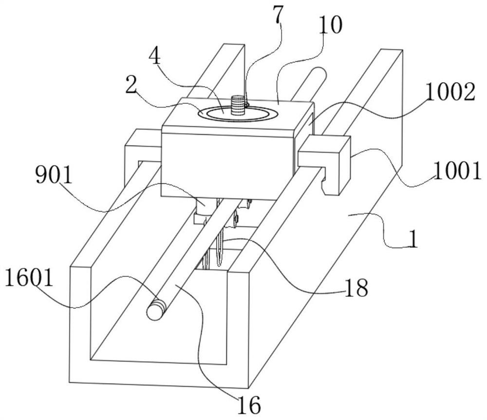
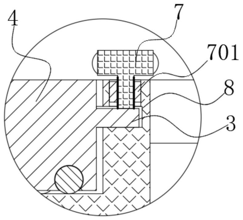
[0004] In order to overcome the problem in the prior art that most of the translation and rotation are hard contacts, which are easy to cause wear and tear and cause harsh sounds, the present invention provides an adjustable camera slide rail

Method used


Image

  • Adjustable camera sliding rail
  • Adjustable camera sliding rail
  • Adjustable camera sliding rail

Examples


Embodiment Construction

[0026] The following will clearly and completely describe the technical solutions in the embodiments of the present invention with reference to the accompanying drawings in the embodiments of the present invention. Obviously, the described embodiments are only some, not all, embodiments of the present invention.

[0027] In describing the present invention, it should be understood that the terms "upper", "lower", "front", "rear", "left", "right", "top", "bottom", "inner", " The orientation or positional relationship indicated by "outside", etc. is based on the orientation or positional relationship shown in the drawings, and is only for the convenience of describing the present invention and simplifying the description, rather than indicating or implying that the referred device or element must have a specific orientation, so as to Specific orientation configurations and operations, therefore, are not to be construed as limitations on the invention.

[0028] In this example

...


PUM


Abstract

The invention belongs to the technical field of camera sliding rails, and particularly relates to an adjustable camera sliding rail. The provided following scheme aims to solving the problem that harsh sounds are generated due to abrasion often caused by hard contact in most horizontal movement and rotation in the prior art. The camera sliding rail comprises a groove-shaped sliding rail with an upward opening and a square tube outer frame slidably connected to the interior of a sliding groove of the groove-shaped sliding rail, end blocks are welded to the two ends of the groove-shaped sliding rail, the same round rod is slidably connected between the two end blocks, two rectangular holes are formed in the position, close to the middle, of the bottom of the square tube outer frame, and telescopic hanging rods are hinged to the positions, located over the rectangular holes, of the inner wall of the top of the square tube outer frame. When the adjustable camera sliding rail is in use, and the square tube outer frame slides on the groove-shaped sliding rail, a lower guide wheel can roll on the surface of the round rod under the action of the telescopic hanging rods, a certain buffering effect is achieved, and therefore, on one hand, sliding abrasion of a certain section often caused by hard contact is avoided, and no harsh metal friction sounds are generated.

Description

technical field [0001] The invention relates to the technical field of camera slide rails, in particular to an adjustable camera slide rail. Background technique [0002] In some cases, the video camera or camera needs to move smoothly for shooting work, which requires the use of a camera slide device. When in use, the camera mechanism is installed on the camera slide device, and the track structure of the slide rail device Just can allow camera mechanism to slide or fix smoothly on the track. At present, most of the common camera slide rails are made of steel or solid rail structure to enhance its stability. The collision also has the problem of high noise during sliding use, which shows that there is a need for further improvement. [0003] After retrieval, the Chinese Patent No. CN202010067828.4 discloses a camera slide rail, which includes a linear guide rail and a movable base connected to the camera equipment. Two upper rails and two lower rails are relatively arrang...

Claims


Application Information

Patent Timeline
IPC IPC(8): F16M11/42
CPCF16M11/425
Inventor 候胖
Owner 候胖
Learn More