Composite leadframe LED package and method of making the same

A lead frame and lead technology used in semiconductor/solid-state device manufacturing, semiconductor devices, electrical components, etc., can solve problems such as affecting reliability

Active Publication Date: 2008-04-30
CREELED INC (N D GES D STAATES DELAWARE NEWARK)
View PDF2 Cites 1 Cited by
  • Summary
  • Abstract
  • Description
  • Claims
  • Application Information

AI Technical Summary

Problems solved by technology

For this reason, when heated, each of these parts undergoes different degrees of thermal expansion, causing mechanical stress between the components of the package, thus adversely affecting its reliability

Method used


Image

  • Composite leadframe LED package and method of making the same
  • Composite leadframe LED package and method of making the same
  • Composite leadframe LED package and method of making the same

Examples


Embodiment Construction

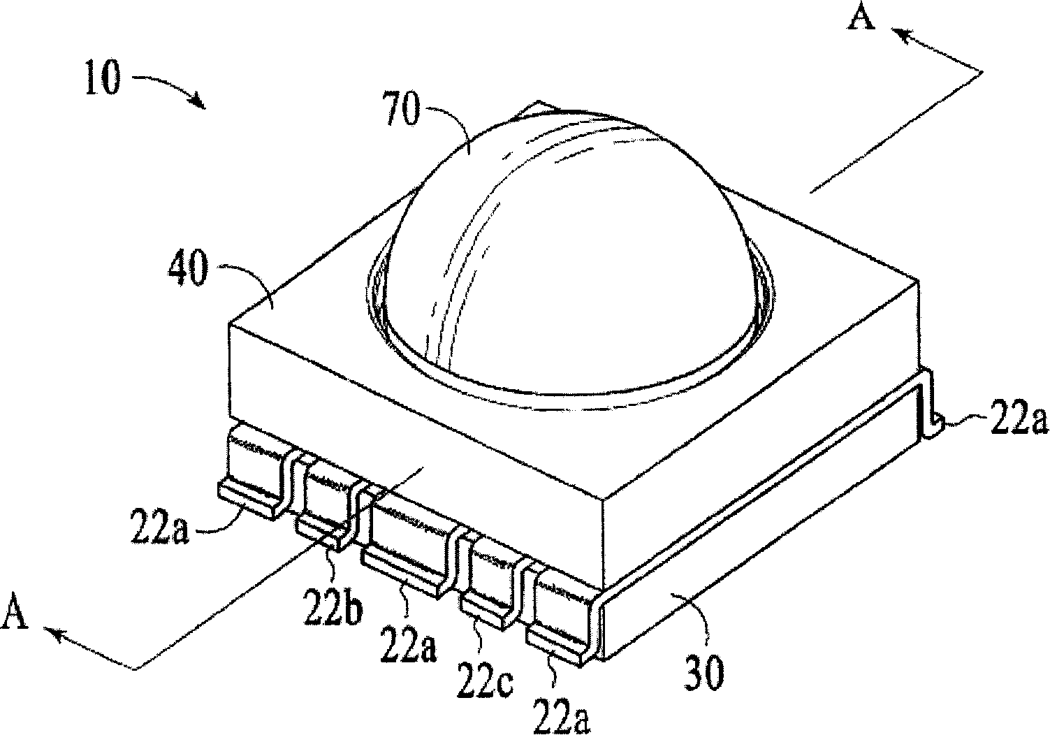
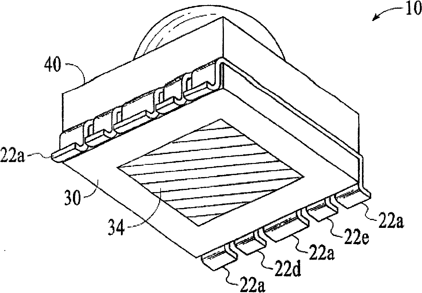
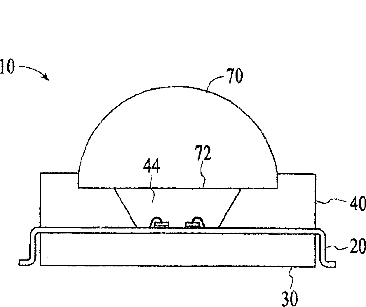
[0018] Reference will now be made to Figures 1 through 1 which illustrate different embodiments of the invention. image 3 The invention is described. As illustrated in the figures, the size of layers or regions are exaggerated for illustrative purposes and thus are provided to illustrate the general structure of the invention. Furthermore, various aspects of the invention are described with reference to structures or portions formed on other structures, portions, or both. It will be apparent to those skilled in the art that reference to a structure formed "on" or "over" another structure or portion encompasses intervenable additional structures, portions, or both. References to a structure formed "on" another structure or portion without an intervening structure or portion are described herein as being formed "directly" on said structure or portion. In addition, relative terms such as "on" or "above" are used herein to describe the relationship of one structure or part to a...


PUM


Abstract

Light emitting die package (10) is disclosed. The die package (10) includes a leadframe (20), a bottom heatsink (30), a top heatsink (40), a reflector (60) and a lens (70). The top and bottom heatsinks (40 and 30) are thermally coupled but electrically insulated from the leadframe (20). The leadframe (20) includes a plurality of leads (22) and defines a mounting pad (28) for mounting LEDS (50). The top heatsink (40) defines an opening (42) over the mounting pad (28). The reflector (60) is coupled to the top heatsink (40) at the opening (42). The lens (70) is placed over the opening (42) defining an enclosed cavity (44) over the mounting pad (28). At least one light emitting diode (50) is mounted on the mounting pad (28) within the cavity (44). Encapsulant optically couples the LED (50) to its surrounding surfaces to maximize its optical Performance. When energized, the LED (50) generates light and heat. The light is reflected by the reflector (60) and operated on by the lens (70). The heat is dissipated by the top and the bottom heatsinks (40 and 30).

Description

[0001] priority [0002] This application claims the benefit of US Provisional Patent Application Serial No. 60 / 431,523, filed December 6, 2002, entitled "Leadframe based LED or semiconductor package with improved heatspreading," granted by the US Patent and Trademark Office. technical field [0003] The present invention relates to the field of packaging semiconductor devices, and in particular to packaging light emitting diodes. Background technique [0004] Light emitting devices (LEDs), such as light emitting diodes, are typically packaged in leadframe packages. Leadframe packages typically include an LED connected to thin metal leads, where the LED and most of the leads are completely encapsulated within a plastic body. A portion of the plastic body defines a lens. A portion of the lead connected to the LED extends outside the plastic body. The metal leads of the leadframe package act as conduits to provide power to the LEDs, and at the same time, they can be used t...

Claims


Application Information

Patent Timeline
IPC IPC(8): H01L21/44H01L25/075H01L33/48H01L33/62H01L33/64
CPCH01L25/0753H01L33/64H01L33/486H01L33/62H01L2224/48091H01L2224/48247H01L2924/00014
Inventor 班·P·罗
Owner CREELED INC (N D GES D STAATES DELAWARE NEWARK)
Why Eureka
Try Eureka