Image recording device

An image recording and image technology, applied in the directions of developing and printing devices, transportation and packaging, photosensitive materials, etc., can solve the problems of inability to transport the photosensitive material 200 straightly, image influence, and inability to transport the photosensitive material 200 straightly, etc.

Inactive Publication Date: 2008-05-28
FUJIFILM CORP
View PDF5 Cites 10 Cited by
  • Summary
  • Abstract
  • Description
  • Claims
  • Application Information

AI Technical Summary

Problems solved by technology

[0014] That is, the pair of transport rollers 202, 204, in order not to make these rotational axes parallel, in a state where the pinching force pinching the photosensitive material 200 is out of balance, since they are in rotational contact with the photosensitive material 200, there is a possibility that the photosensitive material 200 cannot be transported straight. The problem
[0015] In particular, in the exposure process, in the sub-scanning section that requires precise conveyance, the photosensitive material 200 cannot be conveyed straight when the pinching force is out of balance, and there is a problem that the image formed on the photosensitive material 200 is adversely affected.

Method used


Image

  • Image recording device
  • Image recording device
  • Image recording device

Examples


no. 1 Embodiment

[0060] Next, an image recording device including an image recording device according to an embodiment of the present invention will be described with reference to the drawings. Next, the sub-scanning conveyance section, which is a main part of the image recording apparatus, will be described in detail.

[0061] (Overall configuration of the image recording device)

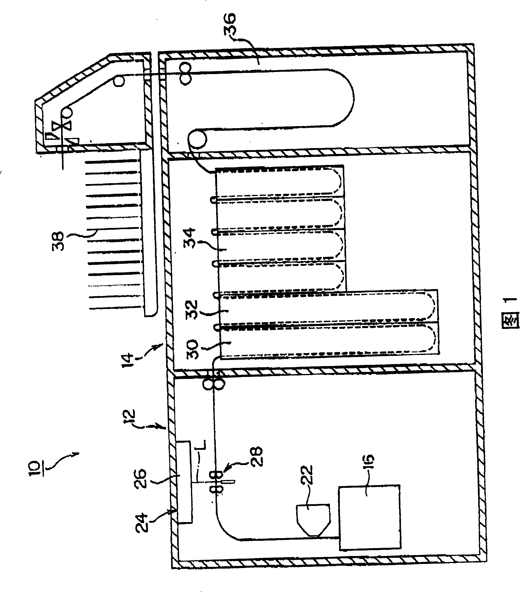
[0062] The image device 10 is mainly used for image formation of a digital photo printer, and is configured as follows, corresponding to image information read by an image reading device such as a film scanner (not shown) and based on exposure conditions determined by a setting device, A printer (image recording device) 12 that forms a latent image by exposing printing paper (photosensitive material) by beam scanning, and a processor 14 that performs a development process on the printing paper on which the latent image is formed and outputs an output print of the recorded film image .

[0063] Printer 12 is shown...

no. 2 Embodiment

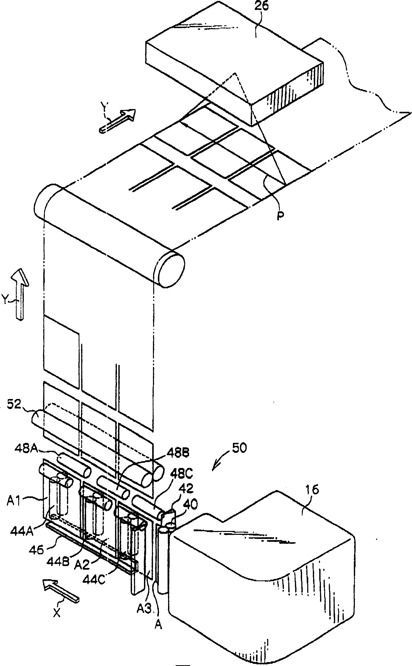
[0087] Next, an image recording device according to a second embodiment of the present invention will be described. In addition, the same reference numerals are assigned to the same constituent elements as those of the first embodiment, and detailed description thereof will be omitted. In addition, since the part different from the first embodiment is only the distributing mechanism 54, only this part will be described.

[0088] As shown in FIG. 6 , the distributing mechanism 54 is provided with three cutters 42A to 42C at predetermined intervals on the transport path instead of the cutter 42 in the first embodiment.

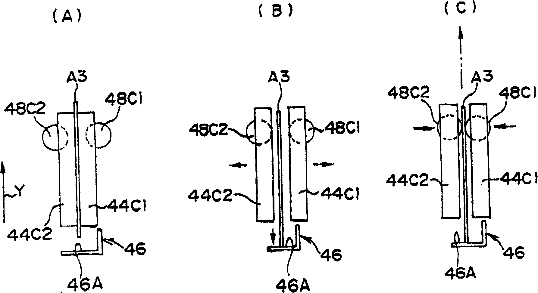
[0089] With such a configuration, the strip-shaped printing paper A pulled out from the paper cassette 16 is conveyed by the first conveyance roller pair 44A to 44C to the farthest first row conveyance position among the three conveyance positions ( Figure 7 to the far left of the , refer to Figure 7 (A)). In this state, the printing paper A is cut by the c...

no. 3 Embodiment

[0094] Next, an image recording apparatus according to a third embodiment of the present invention will be described. Components that are the same as those in the first and second embodiments are given the same reference numerals as those in the first and second embodiments, and detailed description thereof will be omitted. In addition, since the difference from the first and second embodiments is only the distribution mechanism 56, only this part will be described.

[0095] As shown in FIG. 8 , the distribution mechanism 56 is provided with a pair of conveyor belts 60 and 62 instead of the first conveyor roller pairs 44A to 44C of the first and second embodiments.

[0096] Conveyor belt 60 is as shown in Figure 8~ Figure 10 As shown, it consists of tension rollers 64A, 64B and endless conveyor belts 66A, 66B wound around tension rollers 64A, 64B. The endless conveyor belts 66A, 66B are wound around both ends of the tension rollers 64A, 64B, and spaces between which the sec...


PUM


Abstract

An image recording device is an image recording device for exposing a photosensitive material to record image. It is characterized in that the device is provided with a receiving mechanism for receiving the photosensitive material, a first conveying mechanism for conveying the photosensitive material drawn from the receiving mechanism in a first direction and positioning at any position of plurality of conveying positions on the photosensitive material conveying path extending in a second direction crossing with the first direction, and a second conveying mechanism for conveying single or more photosensitive materials positioned on the conveying positions on the conveying path along the second direction by using the first conveying mechanism. The image recording device can distribute the multiple rows of photographic printing papers by simple component, and further can correctly convey the photosensitive material to be conveyed through the conveying path.

Description

technical field [0001] The present invention relates to an image recording device that exposes a photosensitive material and forms an image. Background technique [0002] In recent years, printing devices using digital exposure, that is, photoelectrically read the image recorded on the film, and then use the read image as a digital signal to perform various image processing and use it as image data for recording. Digital photo printers that scan and expose a photosensitive material with modulated recording light for the image data, record an image (latent image), develop it, and output it as a printed product (photograph) are already in practical use. [0003] Such a digital photo printer is basically composed of an input machine having a scanner (image reading device) and an image processing device, and an output machine having a printing device (image recording device) and a developing machine. In the scanner, image projection light captured on the film is photoelectrical...

Claims


Application Information

Patent Timeline
Patent Type & Authority Patents(China)
IPC IPC(8): G03B27/46G03D3/13B65H35/04G03D3/10
CPCG03D3/10G03D3/132
Inventor 森田直之
Owner FUJIFILM CORP
Why Eureka
Try Eureka