
Zero-bias working passive signal isolator

A signal isolator and zero bias technology, which is applied in the direction of instruments, output power conversion devices, and conversion equipment with intermediate conversion to AC, can solve the problems of self-excited oscillation circuit accuracy degradation, etc., to avoid losses, The effect of improving the accuracy of signal transmission

Active Publication Date: 2008-06-04
张姣如
View PDF5 Cites 0 Cited by
  • Summary
  • Abstract
  • Description
  • Claims
  • Application Information

AI Technical Summary

Problems solved by technology

[0003] The purpose of the present invention is to provide a passive signal isolator, which can solve the problem of accuracy deterioration caused by the self-excited oscillation circuit due to shunting from the current loop

Method used


Image

  • Zero-bias working passive signal isolator
  • Zero-bias working passive signal isolator
  • Zero-bias working passive signal isolator

Examples


Embodiment Construction

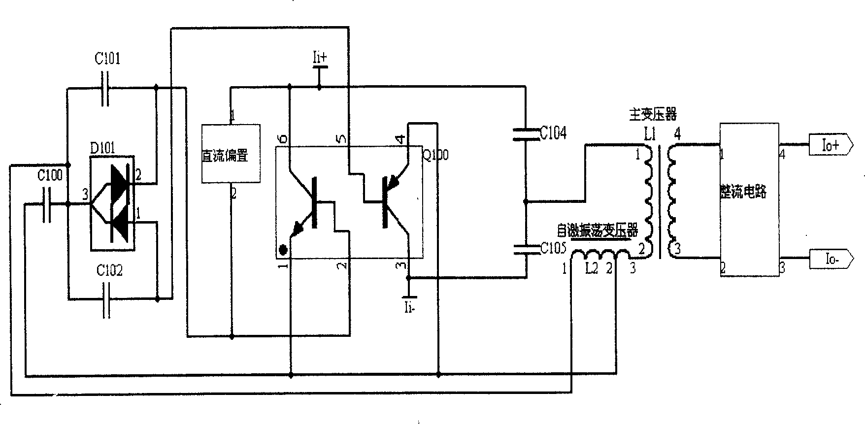
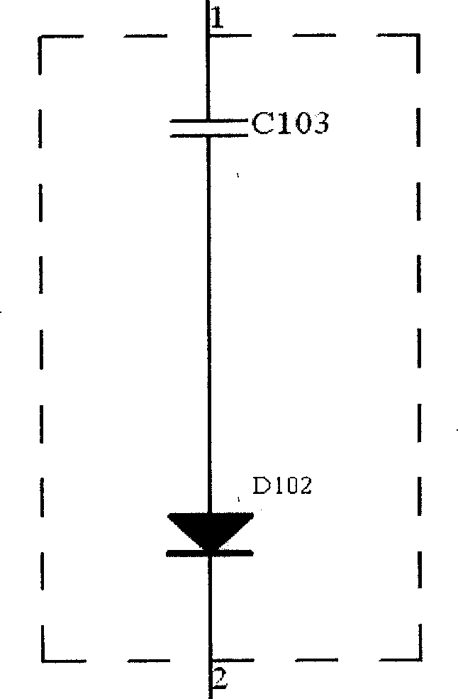
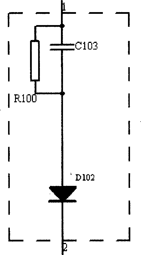
[0013] Such as figure 1 , figure 2 As shown, Ii+ is the positive signal terminal of the current signal input, and Ii- is the negative signal terminal of the current signal input. Q100 is a pair of NPN and PNP complementary transistors, Q100 and capacitors C104 and C105 form a typical DC-DC half-bridge circuit. Capacitors C100, C101, C102 and D101 (double diode series circuit) and transformer L2 form a half-bridge self-excited oscillation circuit. L1 is a 1:1 signal coupling transformer. The secondary of the transformer L1 is connected to the rectification circuit. The DC bias circuit consists of a capacitor C103 and a diode D102 for isolating the self-excited oscillation signal; one end of the capacitor C103 is connected to the current signal input end, one end of the capacitor C103 is connected to the anode of the diode D102, and the cathode of the diode D102 is connected to the triode complementary pair The base of the NPN tube.

[0014] The working principle of the ci...


PUM


Abstract

This invention discloses a passive signal isolator of zero offset work including a self-oscillation circuit, a complementary pair-triode, a DC offset circuit, a transformer and a commutation circuit, in which, one end of the DC offset part is connected to the signal input end and the other end and the output of the self-oscillation circuit are cut in the base of the complementary pair-triode, said DC offset circuit includes a capacitor and a reverse isolating element serial to the capacitor used in isolating self-oscillation signals, one end of the capacitor is connected with the input of the current signals and the positive pole of the reverse isolation element and the reverse pole of the element is connected to the base of the complementary triode. When the circuit is initiated, a little current DC offset to the triode and the DC offset loop is cut off automatically after the start-up and the drive energy of the triode is provided by the oscillation loop of the current circuit so as to avoid loss of current signals.

Description

technical field [0001] The invention relates to a current-type passive signal isolator, in particular to a zero-bias working passive signal isolator. Background technique [0002] Such as figure 1 , in the prior art, the passive signal isolator includes a DC-DC half-bridge circuit composed of complementary triode pairs and capacitors, and a half-bridge self-oscillating circuit mainly composed of D101 (double diode series circuit) and a self-oscillating transformer. Circuit, 1:1 signal coupling main transformer and main transformer secondary rectification circuit, the passive signal isolator chops the input DC signal through the half-bridge circuit and half-bridge self-excited oscillation circuit to make it into an AC signal , and then use the main transformer to couple the energy from the primary to the secondary, and finally rectify the output to drive the load. The self-excited oscillation circuit of the traditional passive signal isolator divides a part of the current f...

Claims


Application Information

Patent Timeline
Patent Type & Authority Patents(China)
IPC IPC(8): H02M3/28H02M3/335
CPCH03H7/52
Inventor 尹向阳磨定敏
Owner 张姣如
Learn More