
Testing device for density variable printed circuit board

A technology of printed circuit boards and test devices, which is applied in the field of test devices that can increase the density of probes, can solve the problems of invariable density and difficulty in testing printed circuit boards, and achieve the effect of increasing test density

Inactive Publication Date: 2008-06-11
UNIMICRON TECH SHEN ZHEN
View PDF4 Cites 0 Cited by
  • Summary
  • Abstract
  • Description
  • Claims
  • Application Information

AI Technical Summary

Problems solved by technology

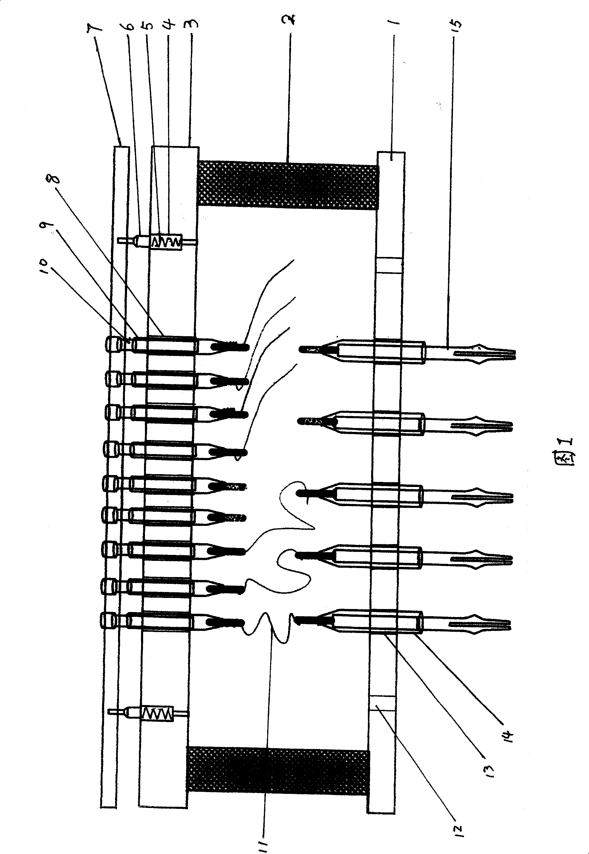
Obviously, the probe array density of this device is consistent with the bushing array density of the testing machine, and is limited by the bushing array density of the testing machine, and its density is invariable, especially cannot be increased
As the density of printed circuit boards increases, it is difficult or impossible for this device to test high-density printed circuit boards

Method used


Image

  • Testing device for density variable printed circuit board
  • Testing device for density variable printed circuit board

Examples


Embodiment Construction

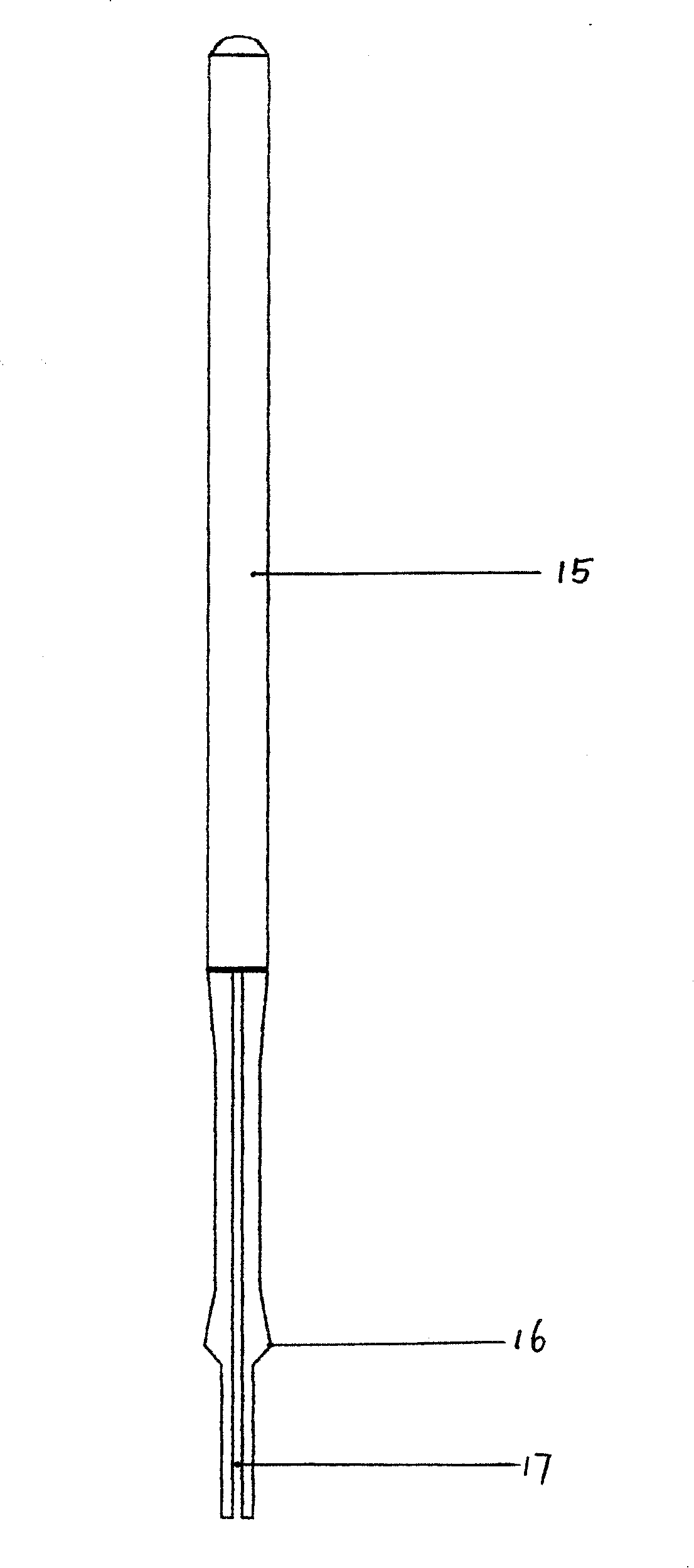
[0011] As shown in Figure 1, this device is used with a printed circuit board testing machine. Place the device on the testing machine, align the positioning hole 12 with the positioning shaft of the testing machine and press down, and the positioning hole 12 will fit on the positioning shaft of the testing machine. , There are at least two positioning holes, so that the device can be positioned accurately. At the same time, the lower end of the transfer terminal 15 is inserted into the sleeve on the testing machine. The upper end of the transfer terminal sleeve 14 is wound with the wire 11, and the other end of the wire 11 is wound with the lower end of the probe sleeve 9, and the connection of the wire 11 is selectively connected according to the test requirements. During the test, the printed circuit board is placed on the upper end of the protection board 7, and the probes 10 are brought into contact with the test points of the printed circuit board, so as to test the elec...


PUM


Abstract

It is a vary-density printing circuit board test apparatus, which is characterized by the following: to have a bottom disc with several cannula holes 13; to fill a cannula 14 in the cannula holes 13; to fill transfer terminal 15 in the cannula 14; to fix a dial plate 3 on top of bottom disc 1; to open several cannula holes 8 in the dial plate3 with its density higher than the density of the cannula holes 13; to fill a cannula 9 in the cannula holes 8 and to fill a probe 10 in the cannula 9; the dial disc 3 and bottom disc 1 are connected by a connection frame 2 and the probe cannula 9 bottom end are selectively connected with the transfer terminal cannula 14 top ends through lead wire 11 according to the measurement.

Description

Technical field: [0001] The invention relates to a device for testing a printed circuit board in cooperation with a printed circuit board testing machine, in particular to a testing device capable of increasing probe density. Background technique: [0002] The currently used test device is provided with a sleeve array on the needle plate, and the sleeve array corresponds to the position of the sleeve array of the measuring machine and has the same density. When testing, first place the needle board on the sleeve array of the testing machine, press down to insert the lower end of the sleeve of the needle board into the upper port of the sleeve of the testing machine, so as to realize the connection with the test circuit of the testing machine; The circuit board is placed on the upper end of the needle board, so that the test points of the printed circuit board are in contact with the probes on the needle board, and the printed circuit board is tested with the testing machine....

Claims


Application Information

Patent Timeline
Patent Type & Authority Patents(China)
IPC IPC(8): G01R1/067G01R1/073H01R4/00G01R31/00G01R31/28
Inventor 邱聪进贾振东杨青松
Owner UNIMICRON TECH SHEN ZHEN
Learn More