Check patentability & draft patents in minutes with Patsnap Eureka AI!

Backlight module

A backlight module and light technology, which is applied in optics, nonlinear optics, instruments, etc., can solve the problem of low light uniformity of the backlight module and achieve the effect of uniform light output

Inactive Publication Date: 2008-06-18
HONG FU JIN PRECISION IND (SHENZHEN) CO LTD +1
View PDF9 Cites 0 Cited by
  • Summary
  • Abstract
  • Description
  • Claims
  • Application Information

AI Technical Summary

Problems solved by technology

[0005] In order to overcome the problem of low light uniformity of the backlight module in the prior art, the present invention provides a backlight module with high light uniformity

Method used


Image

  • Backlight module
  • Backlight module
  • Backlight module

Examples


Embodiment Construction

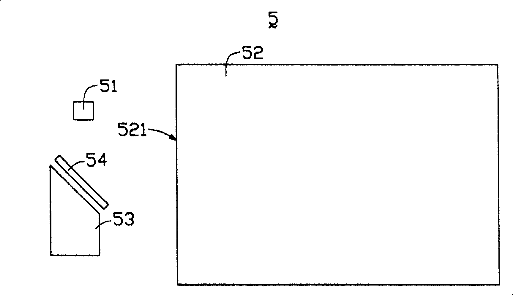
[0012] Such as figure 2 Shown is a schematic plan view of the backlight module of the present invention. The backlight module 5 includes a point light source 51 , a light guide plate 52 and a micro mirror device.

[0013] The point light source 51 is a light emitting diode (Light Emitting Diode, LED), which is used to emit light.

[0014] The light guide plate 52 is a flat light guide plate with a light incident surface 521 .

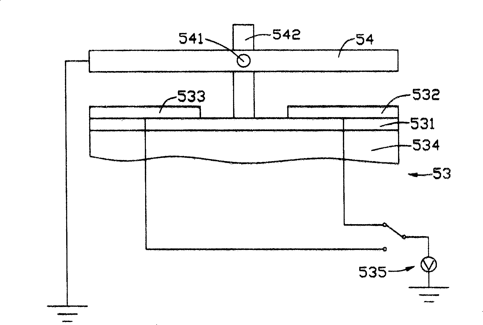
[0015] refer to together image 3 , the micromirror device has a mirror 54 and a driving device 53 . The driving device 53 is a micro-electro-mechanical system (MEMS), which includes a silicon substrate 534 , an insulating layer 531 , an electrode 532 , an electrode 533 and a switching circuit 535 . The driving device 53 is provided with two brackets 542 (only one of which is shown in the figure), and a shaft 541 cooperates with the two brackets 542 , and the reflector 54 is arranged on the shaft 541 . The switching circuit 535 applies a variable ...


PUM


Abstract

The invention relates to a negative phototropic module, which comprises a point light source, a light leading plate and a micro mirror device, wherein the point light source sends the light; the light leading plate possesses a light inlet side; the micro mirror device possesses a reflector and a driving device which can drive the reflecting mirror to rotate; the point light projects to the rotating reflector and reflects to the light inlet side by changing angle.

Description

【Technical field】 [0001] The invention relates to a backlight module applied to a liquid crystal display, in particular to a backlight module with high light uniformity. 【Background technique】 [0002] Since the liquid crystal itself of the liquid crystal display panel does not have light-emitting characteristics, in order to achieve the display effect, it is necessary to provide a light source system for the liquid crystal display panel, such as a backlight module, whose function is to supply the liquid crystal display panel with a surface with sufficient brightness and uniform distribution. light source. [0003] A kind of backlight module of prior art can refer to No. 556,972 of Chinese Taiwan patent announced on October 1, 2003, as figure 1 As shown, the backlight module includes a plurality of light emitting diodes 3 and a light guide plate 1, the light emitted by the plurality of light emitting diodes 3 enters the light guide plate 1 from the light incident surface 11...

Claims


Application Information

Patent Timeline
Patent Type & Authority Patents(China)
IPC IPC(8): G02F1/13357G02F1/1335
Inventor 张仁淙
Owner HONG FU JIN PRECISION IND (SHENZHEN) CO LTD
Features
  • R&D
  • Intellectual Property
  • Life Sciences
  • Materials
  • Tech Scout
  • Unparalleled Data Quality
  • Higher Quality Content
  • 60% Fewer Hallucinations
Learn More