Check patentability & draft patents in minutes with Patsnap Eureka AI!

Backlight module

A backlight module and backplane technology, applied in optics, nonlinear optics, instruments, etc., can solve the problems of shortening the operating life and reducing the luminous efficiency of light-emitting diodes, and achieve the effect of increasing the cross-sectional area

Active Publication Date: 2008-07-02
AU OPTRONICS CORP
View PDF6 Cites 0 Cited by
  • Summary
  • Abstract
  • Description
  • Claims
  • Application Information

AI Technical Summary

Problems solved by technology

[0004] However, with the advancement of LED manufacturing technology, the maximum luminance of light produced by LEDs is also greater. If the number of LEDs used can be reduced, it will also help to save costs, and higher temperatures will reduce luminescence. Diode luminous efficiency and shortened operating lifetime

Method used


Image

  • Backlight module
  • Backlight module
  • Backlight module

Examples


Embodiment Construction

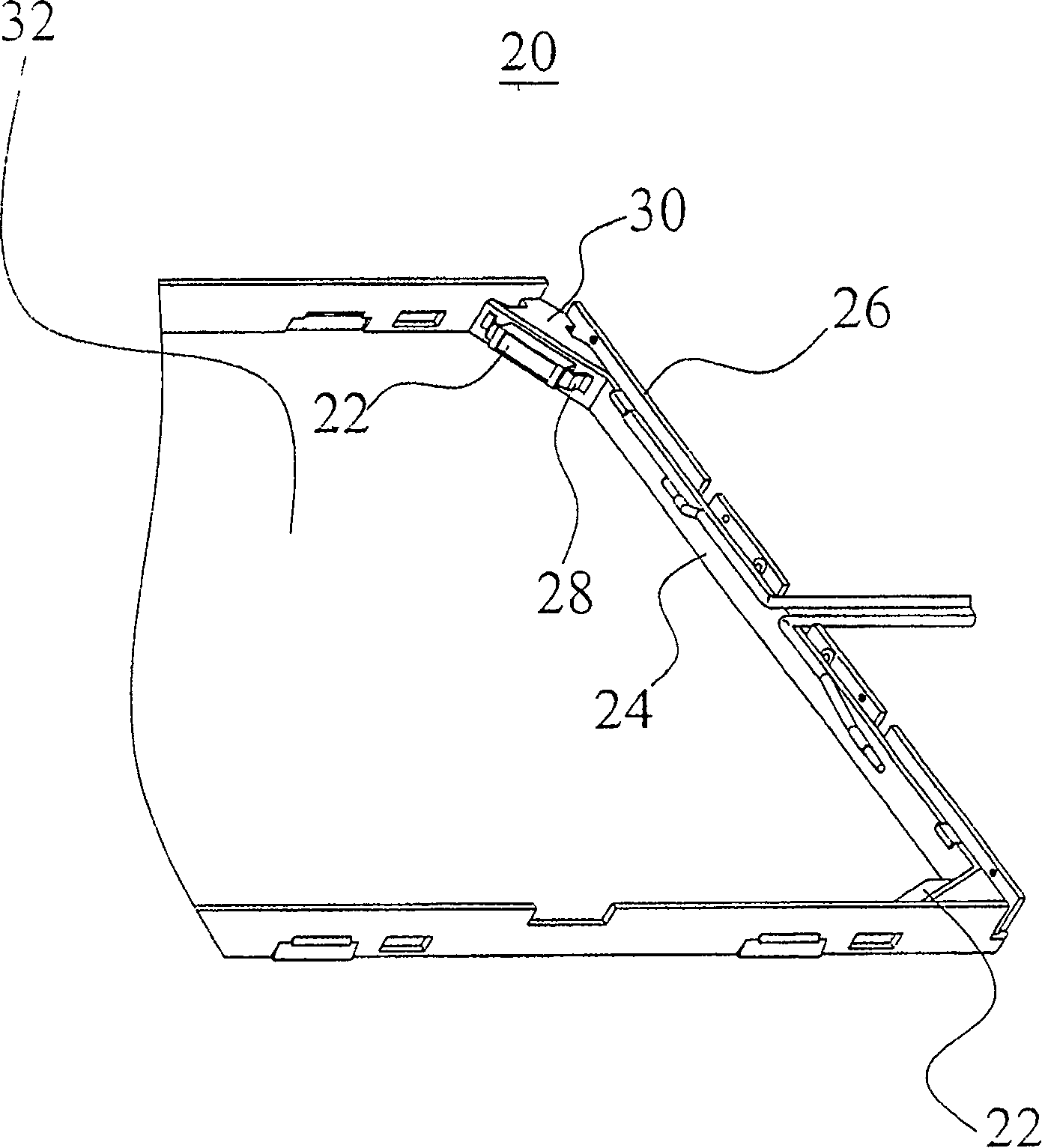
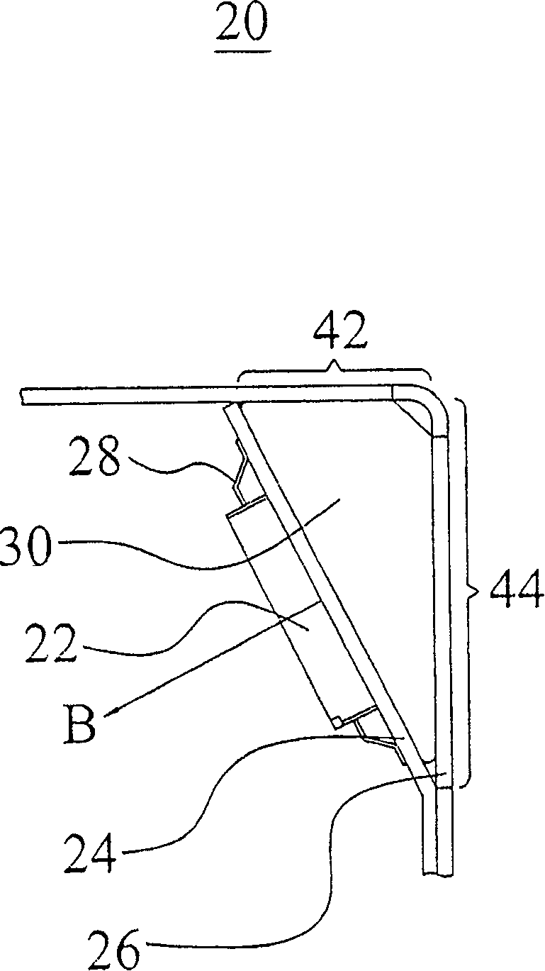
[0019] see figure 2 as well as image 3 , figure 2 is a structural diagram of the backlight module 20 of the present invention, image 3 It is a partial top view of the backlight module 20 of the present invention. The backlight module 20 includes a bezel 26 , and a light emitting diode (LED) 22 is disposed at a corner of the bezel 26 . The bottom surface 32 of the back plate 26 is used to arrange optical elements including a light guide plate, a diffusion sheet, a prism sheet (Brightness Enhancement Film) and the like, which are not shown here to simplify the drawings. These elements are shown. In addition, the LEDs 22 are disposed on a circuit board 24 , and a heat conduction block 30 is disposed between the circuit board 24 and the back plate 26 . The heat conducting block 30 and the back plate 26 can be made of metal (such as aluminum) or other materials with high thermal conductivity.

[0020] When the driving circuit (not shown) of the LED 22 drives the LED 22 to...


PUM


Abstract

The invention discloses a back light module which comprises a back board, at least one light-emitting diode, a light conducting board, a non-rectangle thermal conducting block and a circuit board. The back board has at lease one edge, the light emitting diode is electronically connected on the circuit board, the light emitting diode has a light emitting axis and is placed on the back board edge with the light emitting axis non-parallel or non-vertical with the back board edge. The non-rectangle thermal conducting block is placed between the back board and the light emitting diode for transferring the thermal power generated by the light emitting diode to the back board.

Description

technical field [0001] The invention relates to a backlight module, in particular to a backlight module capable of improving heat dissipation. Background technique [0002] Backlight module (Back light module) is one of the key components of LCD panel (Liquid crystal display panel, LCD panel). Since the liquid crystal itself does not emit light, the function of the backlight module is to supply sufficient brightness and evenly distributed light source. The effective light mechanism converts it into a surface light source with high brightness and uniform luminance to provide the backlight source for the LCD panel. LCD panels have been widely used in electronic products with growth potential such as monitors, notebook computers, digital cameras, and projectors. Especially, large-sized panels such as notebook computers and LCD monitors have the greatest demand. Therefore, backlight modules Demand growth is also growing stronger. [0003] Currently, the light source used in th...

Claims


Application Information

Patent Timeline
Patent Type & Authority Patents(China)
IPC IPC(8): G02F1/13357G02F1/1335
Inventor 吴孟斋罗启忠谢锦坤赖成志郑吉成
Owner AU OPTRONICS CORP
Features
  • R&D
  • Intellectual Property
  • Life Sciences
  • Materials
  • Tech Scout
  • Unparalleled Data Quality
  • Higher Quality Content
  • 60% Fewer Hallucinations
Learn More