Square tubular screw rod transmission lifting lever

A lifting rod and lead screw technology, applied in the directions of transmission devices, electrical components, antenna parts, etc., can solve the problems of inconvenient stable operation of the lifting rod, large margin for left and right rotation, easy to cause danger, etc., and it is beneficial to achieve azimuth stability. , The effect of small azimuth movement margin and good azimuth stability

Active Publication Date: 2008-07-23
北京米波通信技术有限公司
View PDF6 Cites 1 Cited by
  • Summary
  • Abstract
  • Description
  • Claims
  • Application Information

AI Technical Summary

Problems solved by technology

[0003] 1. When the lifting rod is rising or falling, it is easy to slide down and displace after randomly stopping at a certain height, which is inconvenient to work stably at any height of the lifting rod
[0004] 2. During the working process of the lifting rod, when the wire rope is interrupted for some reason, the round aluminum alloy tubes of the rod body will slide down quickly, which is very easy to cause danger
[0005] 3. The steel wire rope is easy to twist after being old and worn, causing the lifting to be stuck and unable to work, and the failure rate is high
[0006] 4. The lowering of the lifting rod is completely completed by the pressure of the loadable object. If there is no heavy load, it needs to be pressed down by manpower, which is troublesome.
[0007] 5. Due to the round appearance of the lifting rod, it is not convenient to install and fix it
[0008] 6. The round aluminum alloy tube of the suit is only fastened up and down with a wire rope, and there is a large margin for left and right rotation, which is not good for the azimuth stability of the top antenna

Method used


Image

  • Square tubular screw rod transmission lifting lever
  • Square tubular screw rod transmission lifting lever
  • Square tubular screw rod transmission lifting lever

Examples


Embodiment Construction

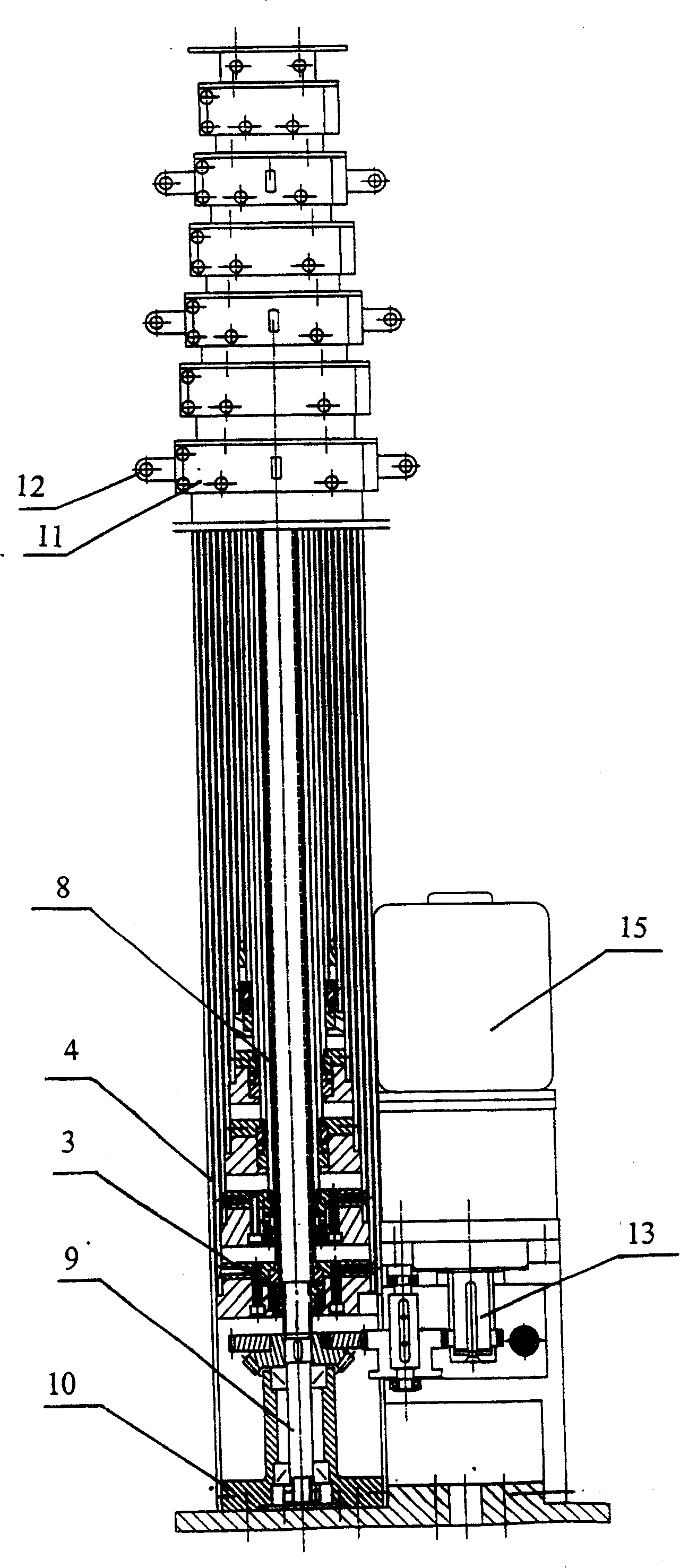
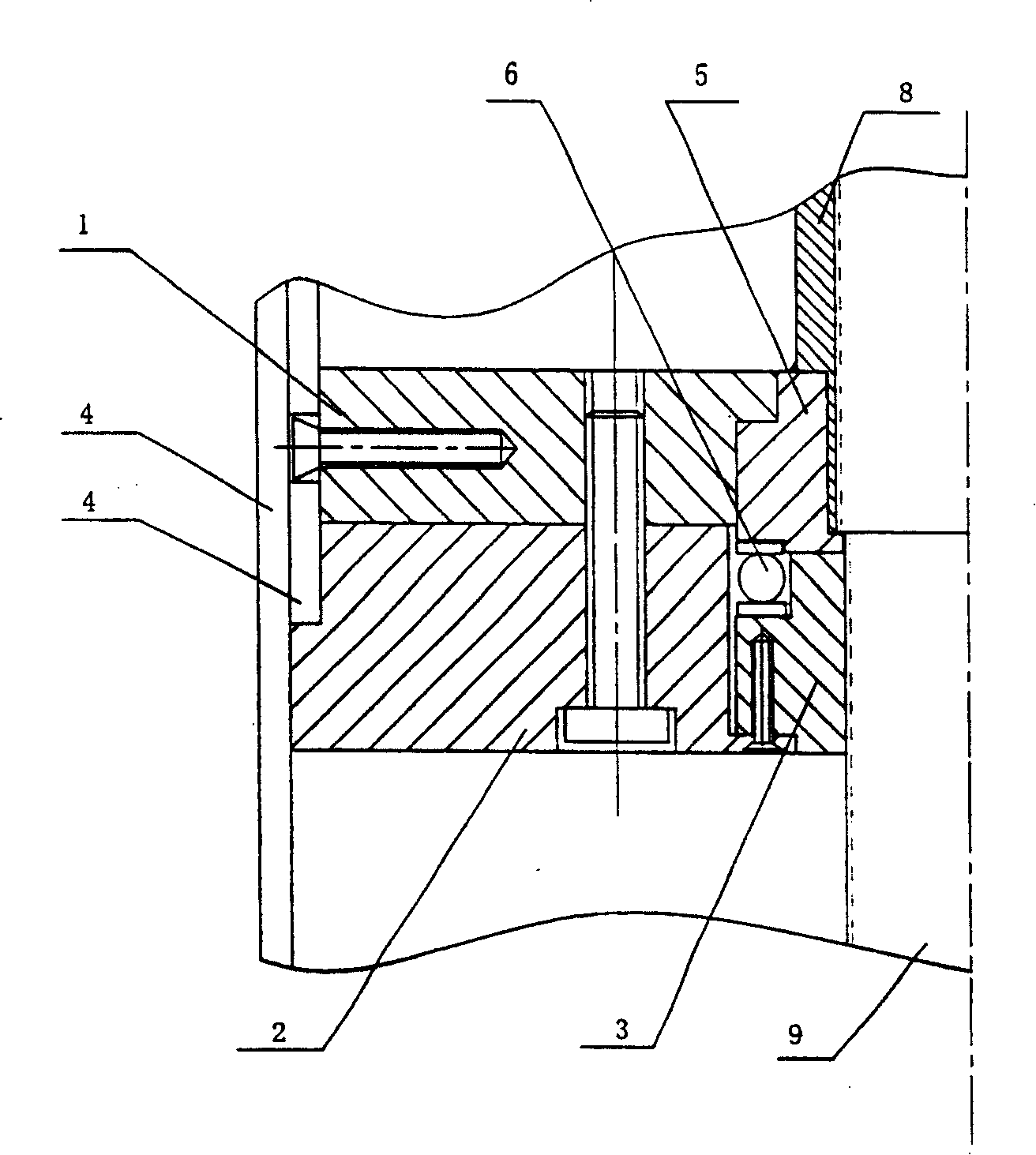
[0033] refer to figure 1 , a screw drive lifting rod of the present invention, which includes: 1 screw 9, 1 chassis 10, 6 nuts 3, 5 screw sleeves 8, 6 positioning blocks 11 and 7 outer sleeves 4. The dimensions of each lead screw cover 8, positioning block 11 and outer casing 4 are different, but the structure is roughly the same; the leading screw 9 is vertically and rotatably seated on the chassis 10, and the positioning block 11 is fixed on the upper end of the outer casing 4, and an outer casing The tube 4 is fitted with another outer sleeve 4 with a gap, the lower end of the outer sleeve 4 is fixed with the lower end of the nut 3 and the lower end of the lead screw sleeve 8, and the nut 3 is threaded with the outer surface of the lead screw sleeve 8 or the lead screw 9 , a lead screw sleeve 8 is fitted together with another lead screw sleeve 8 or lead screw 9 with a gap, and the outer casing 4 is square.

[0034] Four hanging lugs 12 are housed on one of two adjacent pos...


PUM


Abstract

The transmitting lifting arm is composed of the leading screw, chassis and nut. On th leading screw cover at least one locating block, two outer tubes and the leading screws are vertically and rotatably fixed on the chassis, the locating block is fixed on the outer tube. The outer tube is sleeved on the other outer tube with gap, the lower end of the outer tube is fixed with the nut and lower end of the leading screw cover, their spiral are adapting, the leading screw cover is sleeved on the other leading screw cover with gap. The outer tubeis in square shape.

Description

technical field [0001] The invention relates to a screw drive lifting rod, in particular to a square tube screw drive lifting rod used for installation, replacement and maintenance of vehicle-mounted communication equipment such as antennas, cameras and communication machines. Background technique [0002] At present, there are only circular tubular steel wire traction lifting poles used for mounting antennas on vehicles. The lifting poles are set with several sections of aluminum alloy round tubes, pulled by 2 steel wire rope pulleys, and manual work is adopted. The main disadvantages are: [0003] 1. When the lifting rod is rising or falling, it is easy to slide down and displace after randomly stopping at a certain height, which is inconvenient to work stably at any height of the lifting rod. [0004] 2. During the working process of the lifting rod, when the wire rope is interrupted for some reason, the round aluminum alloy tubes of the rod body will slide down quickly, ...

Claims


Application Information

Patent Timeline
Patent Type & Authority Patents(China)
IPC IPC(8): F16H25/20H01Q1/00
Inventor (请求不予公布)
Owner 北京米波通信技术有限公司
Why Eureka
Try Eureka