
Back light module

A technology of backlight module and light guide plate, applied in optics, nonlinear optics, instruments, etc., can solve the problem of uneven light output of backlight module, and achieve the effect of reducing assembly volume, improving light output uniformity, and eliminating dark shadow areas.

Inactive Publication Date: 2008-07-23
HONG FU JIN PRECISION IND (SHENZHEN) CO LTD +1
View PDF15 Cites 0 Cited by
  • Summary
  • Abstract
  • Description
  • Claims
  • Application Information

AI Technical Summary

Problems solved by technology

[0006] In order to overcome the defect of uneven light output of the prior art backlight module, the present invention provides a backlight module with higher light output uniformity

Method used


Image

  • Back light module
  • Back light module
  • Back light module

Examples


Embodiment Construction

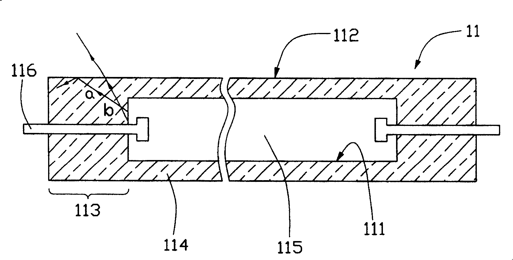
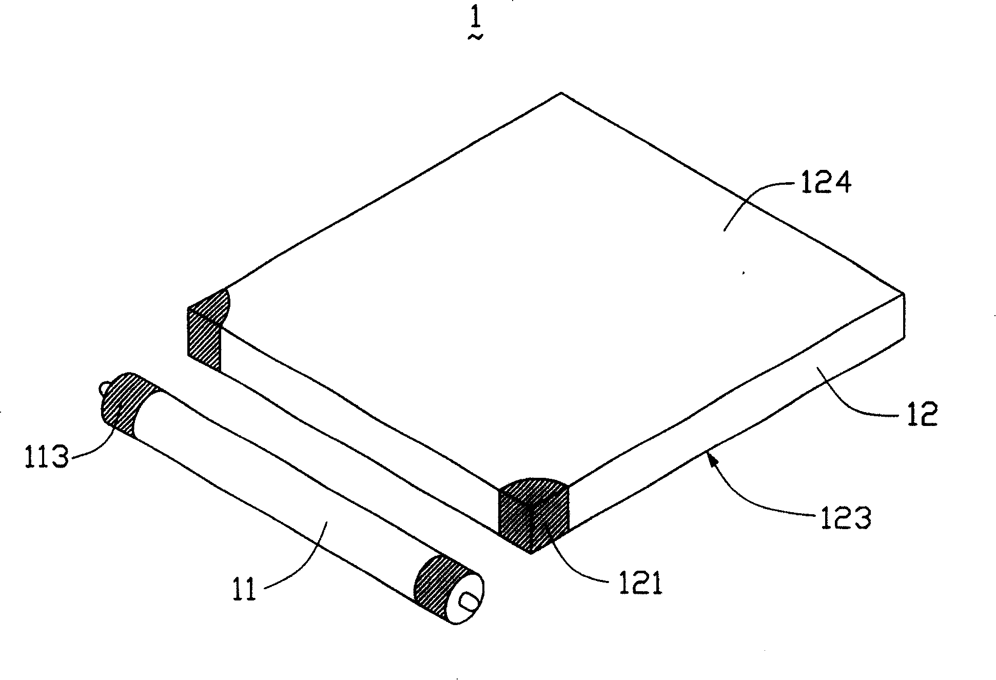
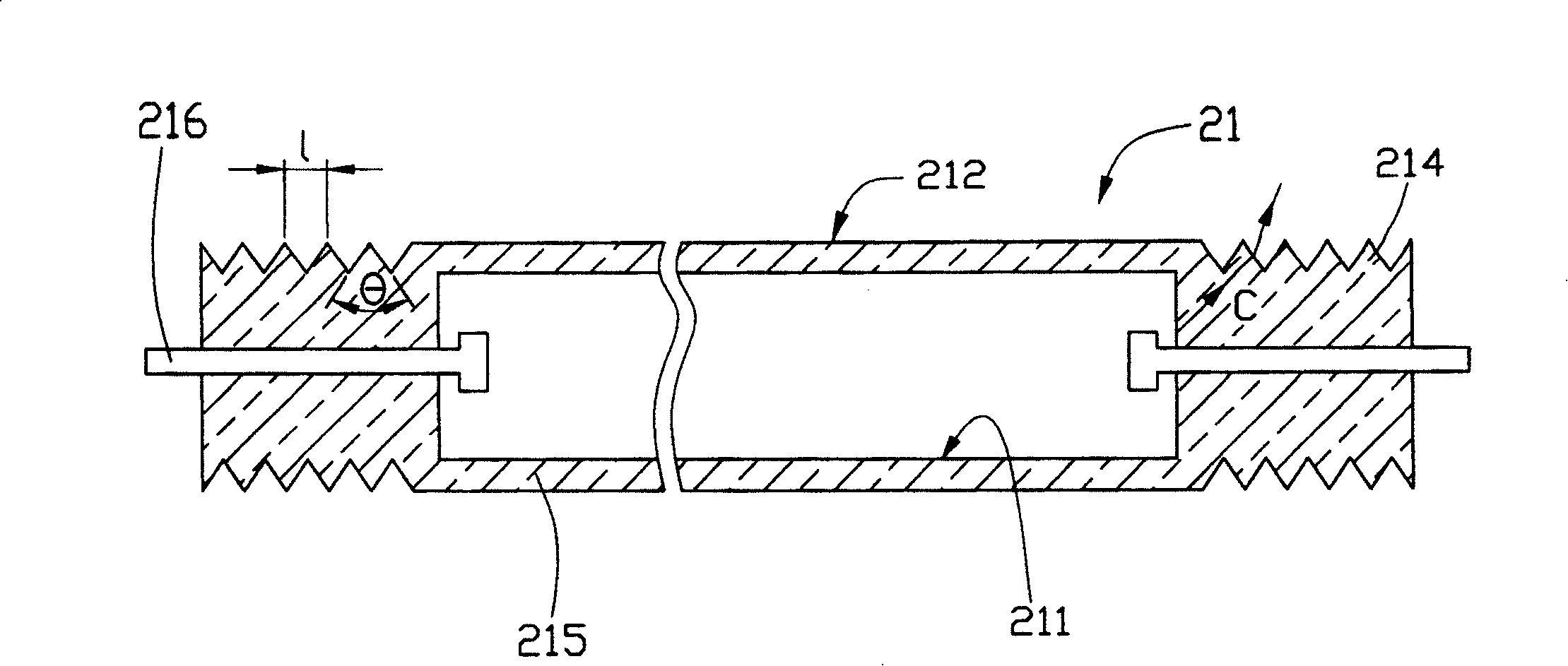
[0013] see image 3 , is a sectional view of the cold cathode fluorescent lamp 21 in the backlight module of the present invention, the cold cathode fluorescent lamp 21 is a closed glass tube 215, the inner side 211 of the tube wall is coated with phosphor (not shown), and the closed glass tube 215 is filled with mercury vapor ( Not shown), wherein the two ends of the closed glass tube 215 are engraved with a plurality of V-shaped grooves 214. The plurality of V-shaped grooves 214 are evenly distributed, and are manufactured by precision machining or photolithography. The pitch L of the V-shaped grooves 214 remains unchanged, the size is 10 μm˜20 μm, and the apex angle θ is 75°˜115°. During operation, a high voltage is applied to the electrodes 216 at both ends to ionize the mercury to emit ultraviolet light, and the ultraviolet light excites the fluorescent material 211 on the inner side of the tube wall to emit visible light. The light c is emitted from the inner side 211 ...


PUM


Abstract

The present invention relates to a kind of back light module including one light guiding board and at least one cold cathode fluorescent lamp. The light guiding board includes at least one incident plane, and the cold cathode fluorescent lamp is set opposite to the incident plane of the light guiding board. The cold cathode fluorescent lamp is one closed glass tube with electrodes inserted to its two ends, and glass tube has V-grooves carved on its two ends.

Description

【Technical field】 [0001] The invention relates to a backlight module, in particular to a backlight module applied to a liquid crystal display. 【Background technique】 [0002] Since the liquid crystal in the liquid crystal display panel itself does not have luminous characteristics, in order to achieve the display effect, it is necessary to provide a backlight module for the liquid crystal display panel. Its function is to provide a surface light source with sufficient brightness and uniform distribution to the liquid crystal display panel. Its operating principle is : The light enters the light guide plate after being emitted from the light source, is reflected by the scattering unit on the bottom surface of the light guide plate and is emitted from the light exit surface of the light guide plate, and cooperates with the enhancement effect of the diffusion plate and the prism sheet to provide a surface light source distribution with sufficient brightness and uniformity. Amon...

Claims


Application Information

Patent Timeline
Patent Type & Authority Patents(China)
IPC IPC(8): G02F1/13357G02F1/1335
Inventor 余泰成吕昌岳陈杰良
Owner HONG FU JIN PRECISION IND (SHENZHEN) CO LTD
Learn More