R2 multifrequency forced signal of DSP on network terminal card

A technology of mandatory signaling and signaling, applied in telephone communication, interconnection devices, monitoring/monitoring/test arrangements, etc., can solve the problems of inflexible adaptation to trunk line protocols and high cost of use

Inactive Publication Date: 2008-07-30
ROCKWELL ELECTRONICS COMMERCE TECH LLC
View PDF4 Cites 0 Cited by
  • Summary
  • Abstract
  • Description
  • Claims
  • Application Information

AI Technical Summary

Problems solved by technology

[0014] While the Acculab Groomer is effective, it is also costly to use and does not provide the fl

Method used


Image

  • R2 multifrequency forced signal of DSP on network terminal card
  • R2 multifrequency forced signal of DSP on network terminal card
  • R2 multifrequency forced signal of DSP on network terminal card

Examples


Embodiment Construction

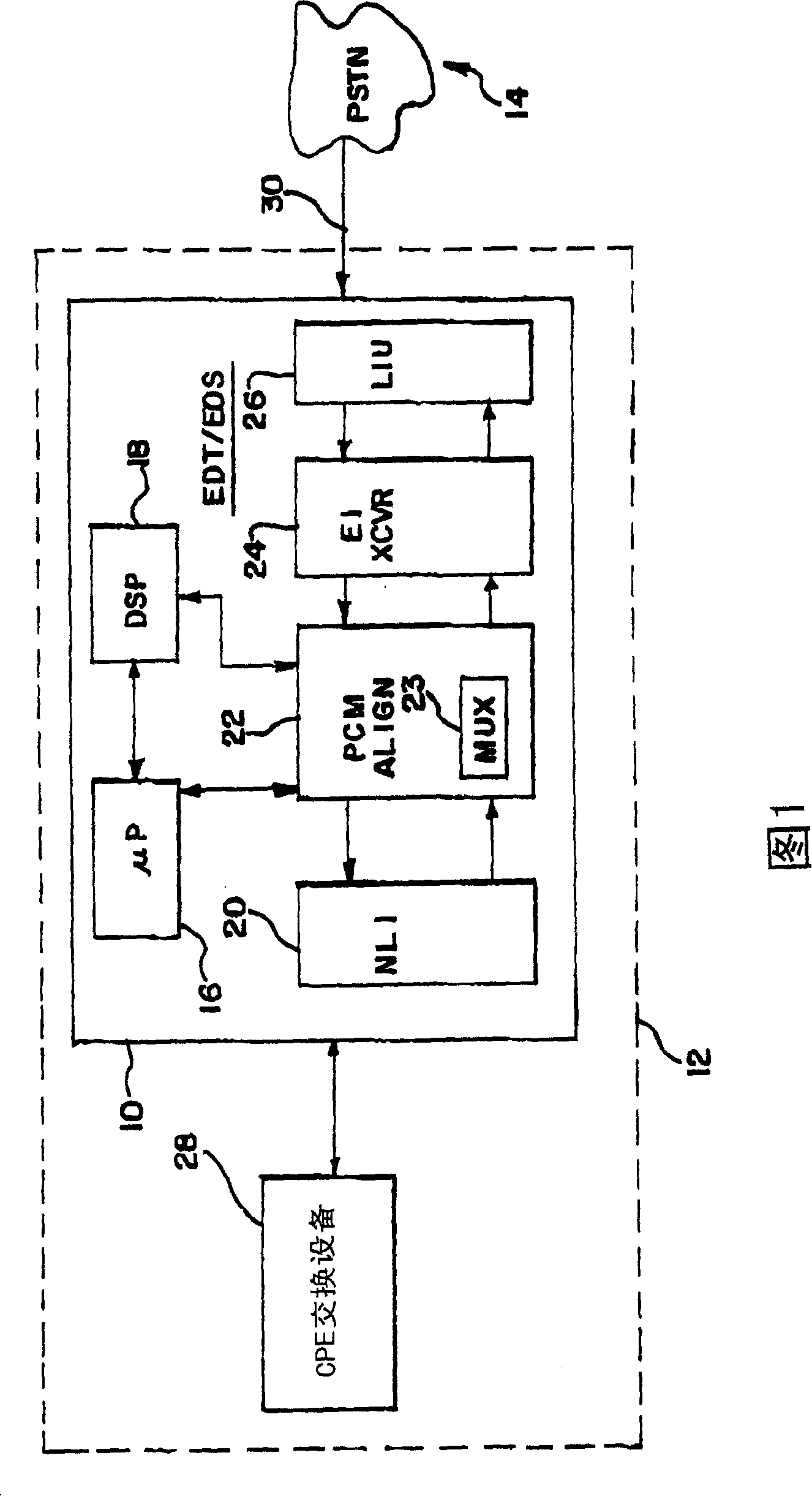
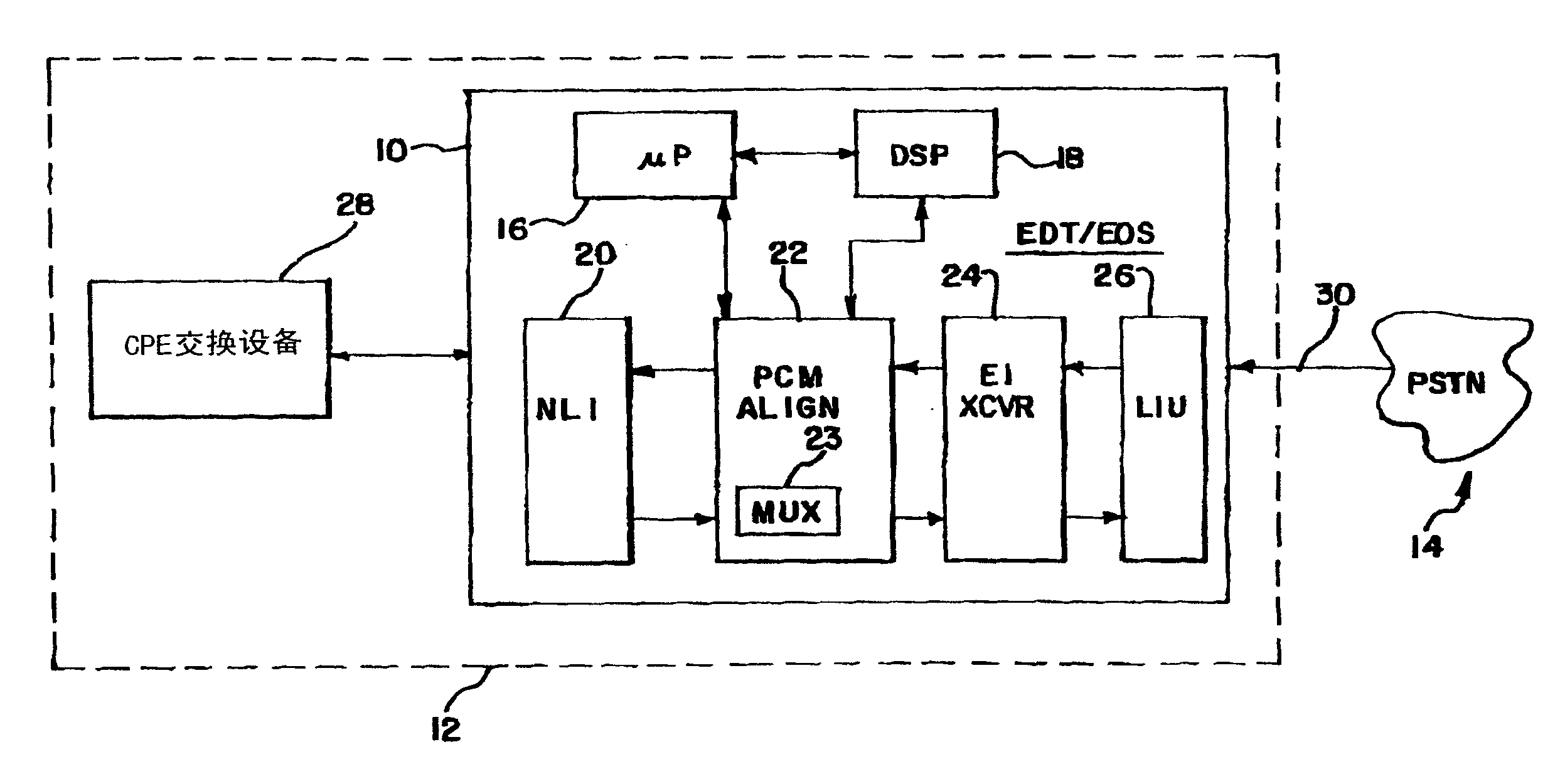
[0019] 1 is a block diagram of an trunk line interface system (EDT / EOS) 10, shown in usage relation, according to one embodiment of the present invention. As shown, the trunk line interface system 10 may be located in customer premises equipment (CPE) (e.g., private branch exchange (PBX), automatic call distributor (ACD), etc.) 12 and used to provide customer premises via interconnecting trunks 30 Interface between equipment (CPE) 12 and public switched telephone network (PSTN) 14 .

[0020] For the purposes of the present invention, PSTN14 may be assumed to be a protocol using R2MFC for intra-switch signaling. The interconnection trunks 30 may be assumed to be E1 type trunks, each providing 32 user channels.

[0021] CPE12 can receive the call from PSTN14 on the subscriber channel, and be used for sending the call to the specific destination in CPE12 according to the call destination information that is provided by the call (for example agent or agent group, predetermined te...


PUM


Abstract

A method and apparatus are provided for processing signals received on a R2 multifrequency compelled signalling subscriber channel within a telephone switch. The method includes the steps of disposing a digital signal processor within the telephone switch between an inbound path of the R2 multifrequency compelled signal subscriber channel and a controlling processor of the telephone switch and detecting an R2 multifrequency compelled signalling control transmission by the digital signal processor on the inbound path. The method further includes the steps of responding to the control transmission by the digital signal processor transmitting an acknowledgement on an outbound path of the subscriber channel and transferring a symbolic representation of the control transmission to the controlling processor of the switch.

Description

technical field [0001] The field of the invention relates to telephone systems, and more particularly to the processing of call control signals at an exchange in a telephone system. Background technique [0002] The use of R2 Multi-Frequency Force Signaling (R2 MFC) in telephony systems is known. R2 MFC is an in-band signaling protocol that uses a combination of frequencies to convey information. Although it is similar to a dual-tone multi-frequency (DTMF) system that uses a combination of frequencies to transmit information, R2 MFC provides additional functionality suitable for signaling between switches. [0003] More specifically, DTMF is commonly used to send dialing information from a subscriber's telephone to a local central office (CO). Therefore DTMF is generally limited to transmitting the digits 0 to 9, # and *. If a single digit is not received by the CO or received incorrectly, the result is a misdialed number or the familiar voice message: "The call was not c...

Claims


Application Information

Patent Timeline
IPC IPC(8): H04M3/00H04M3/22H04M7/00H04Q1/45H04Q3/00
CPCH04M7/0096H04Q3/0025H04Q1/45H04M3/22
Inventor 巴里·W·琼斯丹尼尔·F·贝克
Owner ROCKWELL ELECTRONICS COMMERCE TECH LLC
Why Eureka
Try Eureka