
Eureka
For R&D, Eureka makes reading and utilizing patents & technical documents easy.
Eureka AIR
Designed for self-driven R&D workflows. Generate viable solutions, solve complex R&D challenges, empower your innovation with AI.

Eureka Materials
Designed for material experts only. Revolutionize your material R&D, from search, analyze, to developing new materials.

TechResearch
Generate reliable direction feasibility study reports for your R&D in just a few steps.

TechSeek
Discover and master advanced knowledge NOW. Basics, ideas, possibilities, all at once.

TechMind
As an expert in R&D Theories, TechMind can generates customized viable solutions instantly.

TechRisk
Analyze your overall solution with one click, know your potential R&D risks in advance.

TechMonitor
Get weekly tech updates, stay abreast of the latest tech innovations and key insights.
Method for recording data on optical record carrier
A technology for optical recording and data recording, which is applied to optical recording carriers, optical recording/reproducing/erasing methods, optical recording systems, etc., and can solve problems such as tracking control damage, focus control and data reproduction operations being affected
- Summary
- Abstract
- Description
- Claims
- Application Information
AI Technical Summary
Problems solved by technology
Method used
Image

Examples
no. 1 example
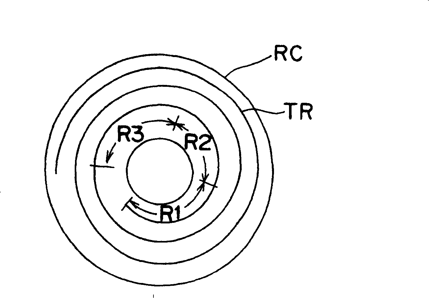
[0070] In FIG. 5 there is shown a recording apparatus according to the invention for recording randomized data on a sector Sm of an optical disc RC'. This disc RC' is figure 1 A modification of the optical disc RC, it is a data writable (rewritable) medium. The data format and track structure of the two optical discs RC and RC' are basically the same.
[0071] The recording unit WA includes a disk motor 102 for supporting and rotating figure 1The disc RC'. An optical head 104 optically writes data on the optical disc RC'. The optical head 104 includes a light source 104a, a light modulator 104b, a focusing unit 104c, a half mirror 104d, and a photodetector 104e.
[0072] The light source 104a emits a light beam Ls to the optical disc RC' through the light modulator 104b, the half mirror 104d, and the focusing unit 104c. The light modulator 104b is driven by the light modulator driver 110 so as to modulate the intensity of the light or its emission angle to prevent the l...
no. 2 example
[0170] Refer to the following Figure 14 and 15 The recording apparatus and reproducing apparatus according to this embodiment will be described. It should be noted that the recording apparatus WA and the reproducing apparatus RA according to this embodiment differ from those in the first embodiment only in the data formatter and data deformatter. Therefore, a detailed description of parts of these devices other than the data formatter and data deformatter is omitted for the sake of brevity.
[0171] exist Figure 14 expressed in Figure 6 A variant of the data formatter 122. Another data formatter 122R according to this embodiment includes the same components as the data formatter 122, but the positions of the ECC check byte generator 503 and the scrambler 504 are reversed. Specifically, as clearly shown in FIG. 9, in this data formatter 122R, an ECC check byte generator 503 is connected to a scrambler 504, which in turn is connected to a header data generator 502.
[0...
PUM
| Property | Measurement | Unit |
|---|---|---|
| thickness | aaaaa | aaaaa |
Abstract
Description
Claims
Application Information
 - R&D Engineer
- R&D Manager
- IP Professional
- Industry Leading Data Capabilities
- Powerful AI technology
- Patent DNA Extraction
Browse by: Latest US Patents, China's latest patents, Technical Efficacy Thesaurus, Application Domain, Technology Topic, Popular Technical Reports.
© 2024 PatSnap. All rights reserved.Legal|Privacy policy|Modern Slavery Act Transparency Statement|Sitemap|About US| Contact US: help@patsnap.com