Pneumatic tailstock of numerically controlled lathe

A technology of CNC lathes and tailstocks, which is applied in the direction of tailstocks/tops, turning equipment, tool holder accessories, etc., which can solve the problems of axial clearance, reduce the service life of equipment, and reduce machining accuracy, so as to achieve low rolling friction coefficient, The effect of high mechanical movement precision and small guide gap

Inactive Publication Date: 2008-10-01
盛焕君
View PDF6 Cites 0 Cited by
  • Summary
  • Abstract
  • Description
  • Claims
  • Application Information

AI Technical Summary

Problems solved by technology

Its disadvantages are as follows: firstly, this kind of manual adjustment has low work efficiency, high labor intensity for the operator, and frequent axial slip adjustment of the shaft sleeve, which accelerates the friction and wear between the tailstock and the shaft sleeve, forming a gap, which directly affects The processing accuracy of parts and reduce the service life of equipment; secondly, the choice of live thimble or dead thimble depends on the processing speed and accuracy. Easy to bite to death; when processing at low speed, the accuracy of the parts is required to be high, so choose dead thimbles
Due to structural reasons, the live thimble has poor rigidity and low life, and it is easy to cause axial clearance, which reduces the machining accuracy.

Method used


Image

  • Pneumatic tailstock of numerically controlled lathe
  • Pneumatic tailstock of numerically controlled lathe
  • Pneumatic tailstock of numerically controlled lathe

Examples


Embodiment Construction

[0017] The embodiments of the present invention will be described in detail below in conjunction with the accompanying drawings.

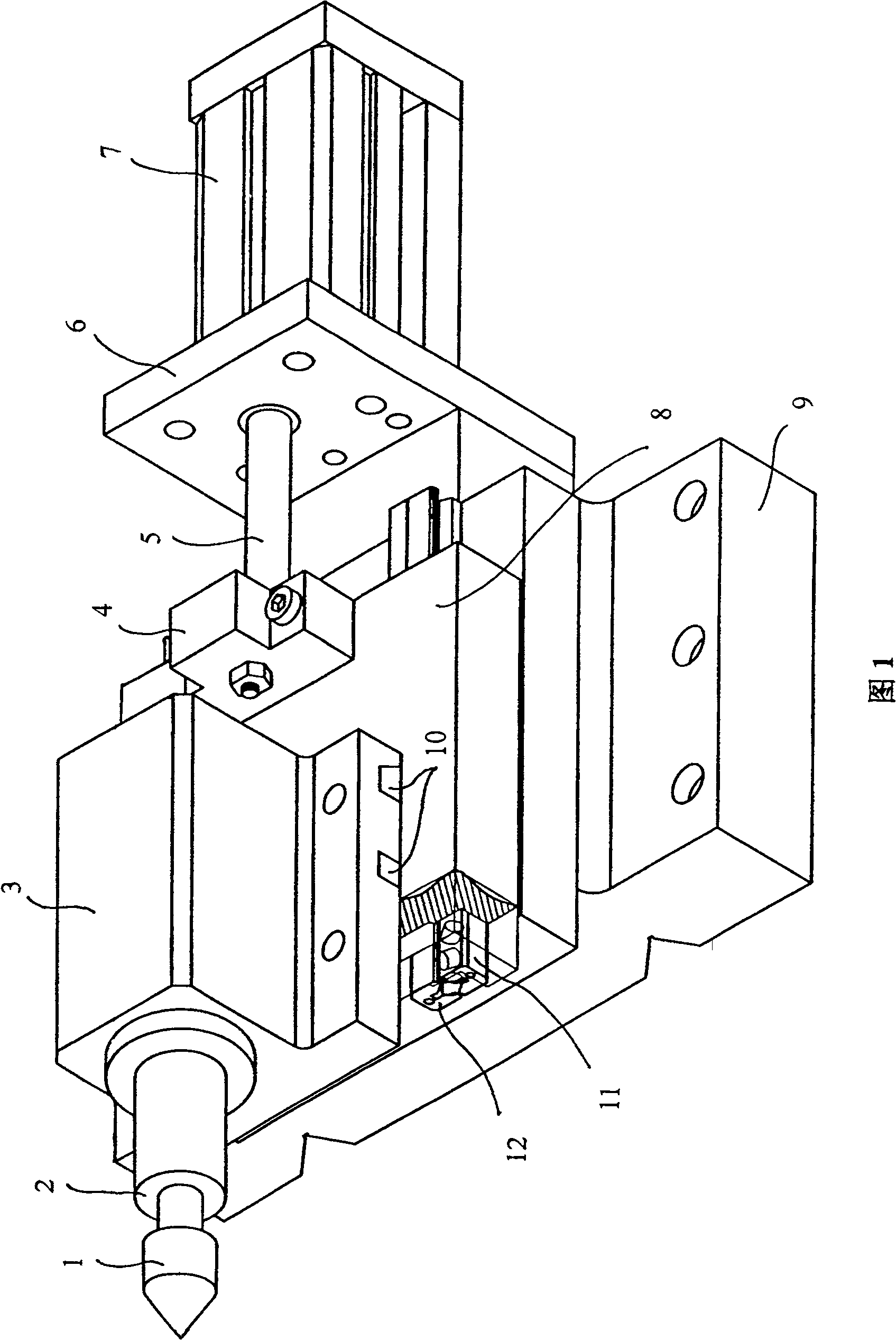
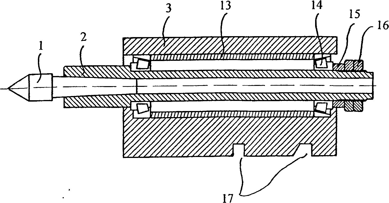
[0018] As shown in Figures 1 to 4, the CNC lathe pneumatic tailstock includes a base 9 installed on the guide rail of the CNC lathe. The two guide rail grooves on the bottom surface of the base can be adjusted axially along the lathe guide rail, especially when processing short materials. Adjust accordingly, and fix the base after adjustment.

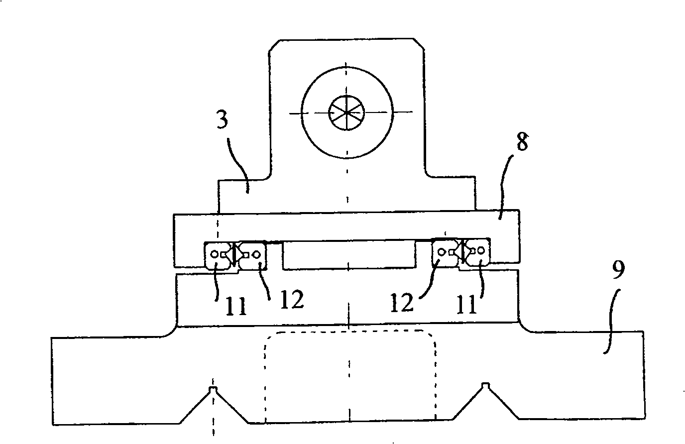
[0019] The carriage 8 is arranged on the top of the base, and can be adjusted for axial sliding relative to the base. The sliding adjustment is realized by a pair of rolling guide rails arranged between the base and the carriage. The pair of rolling guide rails described in this application are The patent structure of the patent No. 02260472.3 obtained by the person first, the rolling friction part of the rolling guide rail is composed of a fixed guide rail 12 and a rolling guide rail 11 with a cage 19 separ...


PUM


Abstract

The pneumatic tailstock of numerically controlled lathe includes a pedestal, a carriage, rolling guide rails for the pedestal and the carriage to be installed on, a muff for installing thimble on bearing with great bearing capacity, a connecting seat fixed on the carriage, and computerized control system with pneumatic control element connected to the connecting seat. The present invention has improved tailstock structure, less contact and less wear between the muff and the tailstock, high precision, simple operation, high operation efficiency and other advantages.

Description

technical field [0001] The invention relates to a tailstock structure of a numerically controlled lathe, in particular to a pneumatic tailstock of a numerically controlled lathe which realizes pneumatic advance and retreat adjustment. Background technique [0002] When the CNC lathe is processing parts, one end is clamped by the spindle box chuck, and the other end is supported by the tailstock thimble. Because the tailstock is fixed after the large adjustment position is determined, and the thimble needs to be pressed before it withstands the processed parts. Small axial adjustments are required and are accomplished by axial adjustment of the shaft sleeve on which the thimble is mounted. The shaft sleeve in the prior art is achieved by shaking the handle of the tailstock. The axial position of the thimble is determined by the sliding distance of the shaft sleeve in the tailstock. One turn, the shaft sleeve drives the thimble to expand and contract by 4 to 6 mm, and then lo...

Claims


Application Information

Patent Timeline
Patent Type & Authority Patents(China)
IPC IPC(8): B23B23/00
Inventor 盛焕君
Owner 盛焕君
Why Eureka
Try Eureka