External multi-point inductive flow sensor
A flow sensor and multi-point sensing technology, which is applied in the field of flow sensors, can solve the problems of poor versatility and large noise mixed in the output signal, and achieve the effect of simple structure, large range and high measurement sensitivity
- Summary
- Abstract
- Description
- Claims
- Application Information
AI Technical Summary
Problems solved by technology
Method used
Image
Examples
Embodiment 1
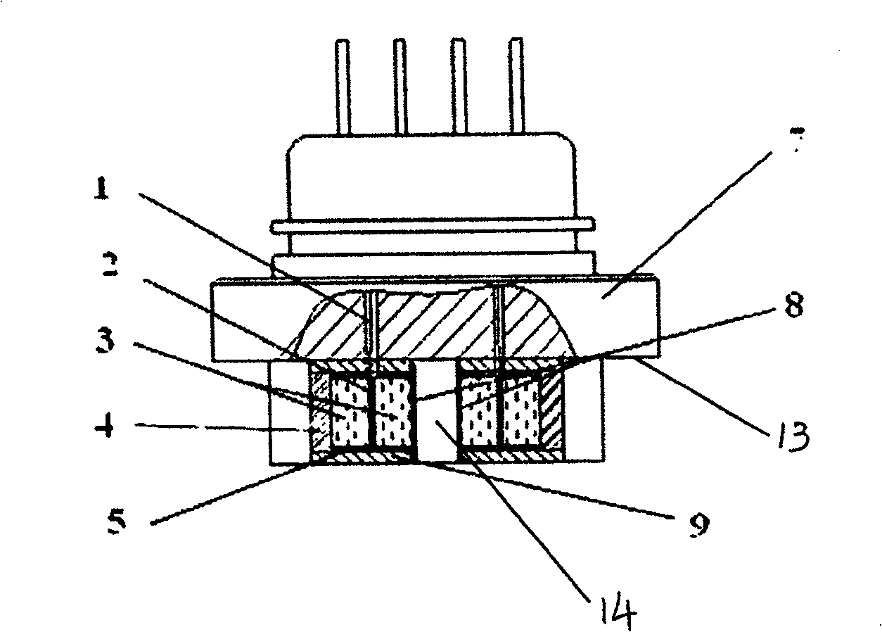
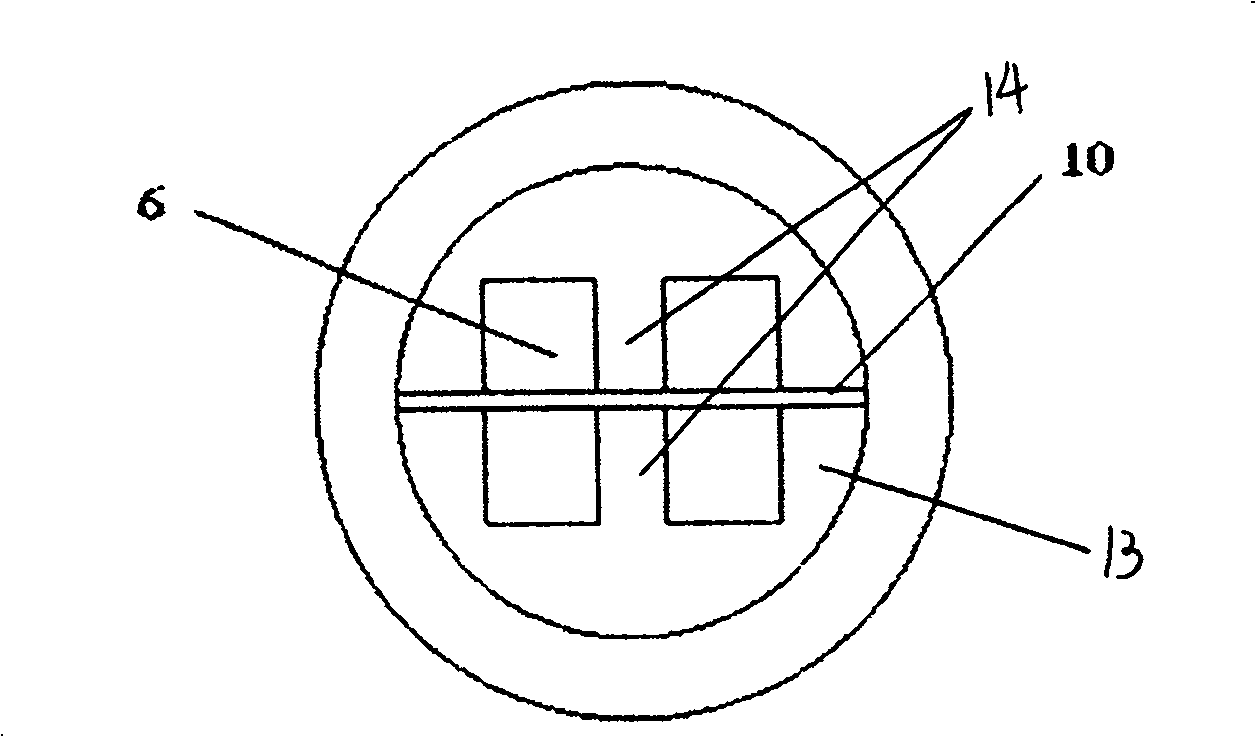
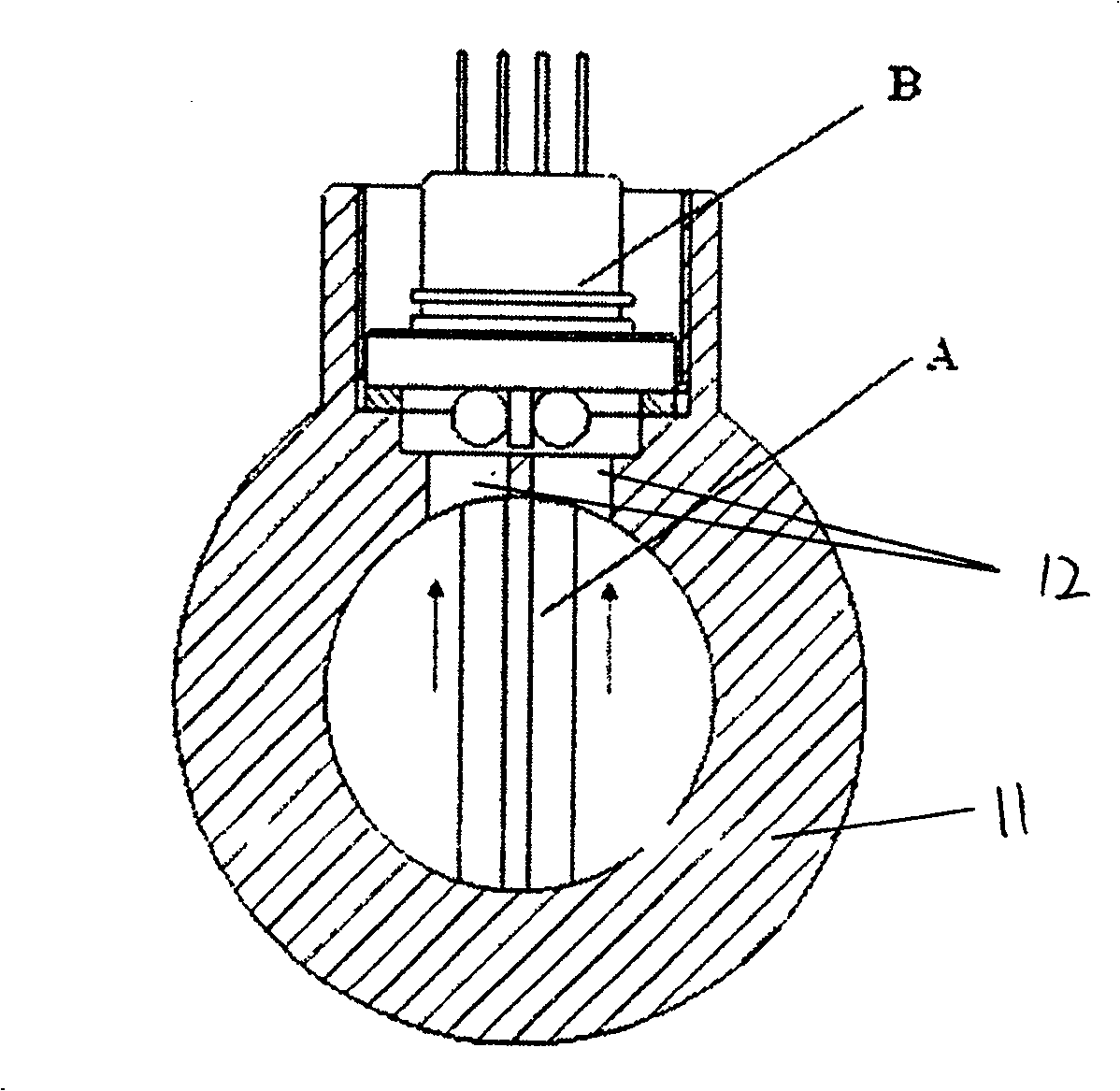
[0022] as attached figure 1 , 2 , 3 and 4, an external multi-point induction flow sensor includes a structural body 7 and two pairs of detection units 6 arranged on the bottom of the structural body 7, the structural body 7 is placed in the pipeline 11 wall of the sensor, Two pressure guiding holes 12 are provided on the wall of the pipeline 11, through which the detection unit 6 senses the alternating stress of the vortex generator, and the structural body 7 is placed in the wall of the sensor pipeline 11, making the sensor more versatile. The bottom surface 13 of the structural body 7 is provided with a partition 10 arranged along the fluid flow direction X, that is, along the axial direction of the pipeline 11. A pair of detection units 6 are symmetrically distributed on both sides of the partition 10. The detection unit 6 It is cylindrical, and the height of the partition 10 is the same as the diameter of the detection unit 6 . The detection unit 6 includes a housing 9, ...
Embodiment 2
[0031] as attached Figure 5 As shown, an external multi-point induction flow sensor includes a structural body 7, the bottom surface 13 of the structural body 7 is provided with a partition 10, and two pairs of detection units 6 are respectively welded in the horizontal direction on both sides of the partition 10, and the two pairs of detection units The units 6 are arranged in a row along the axial direction of the pipeline 11. There is a gap between two adjacent detection units 6. The length of the partition is greater than the total length of the four detection units, and the height of the partition is the same as the diameter of the detection unit. All the other are the same with embodiment 1.
Embodiment 3
[0033] Such as Figure 6 As shown, an external multi-point induction flow sensor includes a structural body 7, the bottom surface 13 of the structural body 7 is provided with a partition 10, and two pairs of detection units 6 are respectively welded in the vertical direction on both sides of the partition 10. The detection units 6 are arranged along the radial direction of the pipeline 11 , the length of the partition is slightly greater than the total length of the two detection units 6 , and the height of the partition is greater than twice the diameter of the detection unit 6 . All the other are the same with embodiment 1.
PUM
 Abstract
Description
Claims
Application Information
 - R&D
- Intellectual Property
- Life Sciences
- Materials
- Tech Scout
- Unparalleled Data Quality
- Higher Quality Content
- 60% Fewer Hallucinations
Browse by: Latest US Patents, China's latest patents, Technical Efficacy Thesaurus, Application Domain, Technology Topic, Popular Technical Reports.
© 2025 PatSnap. All rights reserved.Legal|Privacy policy|Modern Slavery Act Transparency Statement|Sitemap|About US| Contact US: help@patsnap.com


