

Heating to conatant temperature type equipment for reloading methanol
A methanol decomposition and reforming device technology, applied in the direction of inorganic chemistry, non-metallic elements, chemical instruments and methods, etc., can solve problems such as cold start difficulties, achieve improved cold start performance, fast flame propagation speed, and reduce exhaust pollution Effect
Inactive Publication Date: 2008-10-22
郑国璋
View PDF3 Cites 0 Cited by
- Summary
- Abstract
- Description
- Claims
- Application Information
AI Technical Summary
Problems solved by technology
At present, engines burning methanol have problems with cold start difficulties and harmful formaldehyde, an intermediate product of methanol combustion, in emissions.
Method used
View moreImage
Smart ImageViewing Examples

Examples
Embodiment Construction
[0013] specific implementation plan
Login to View More PUM
 Abstract
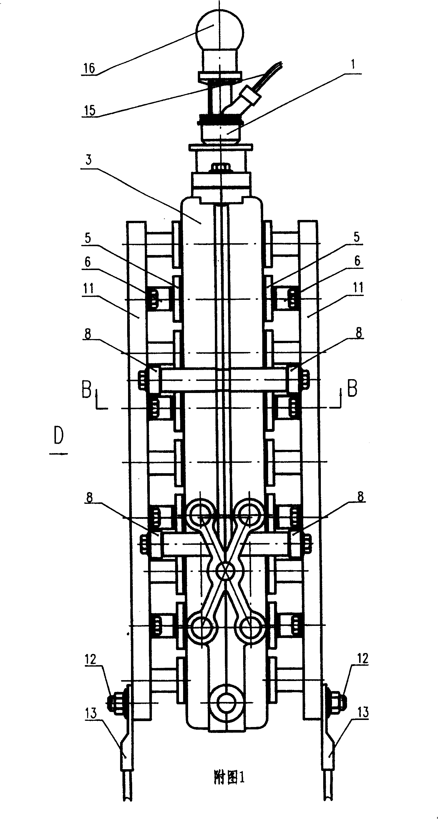
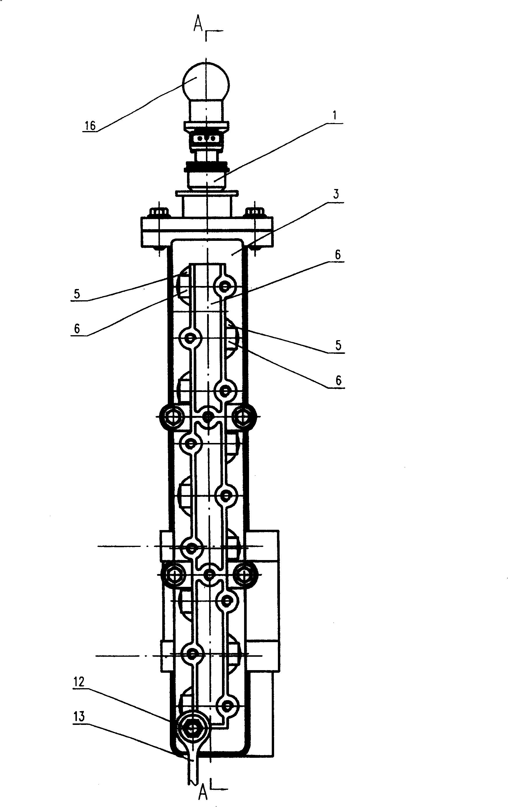
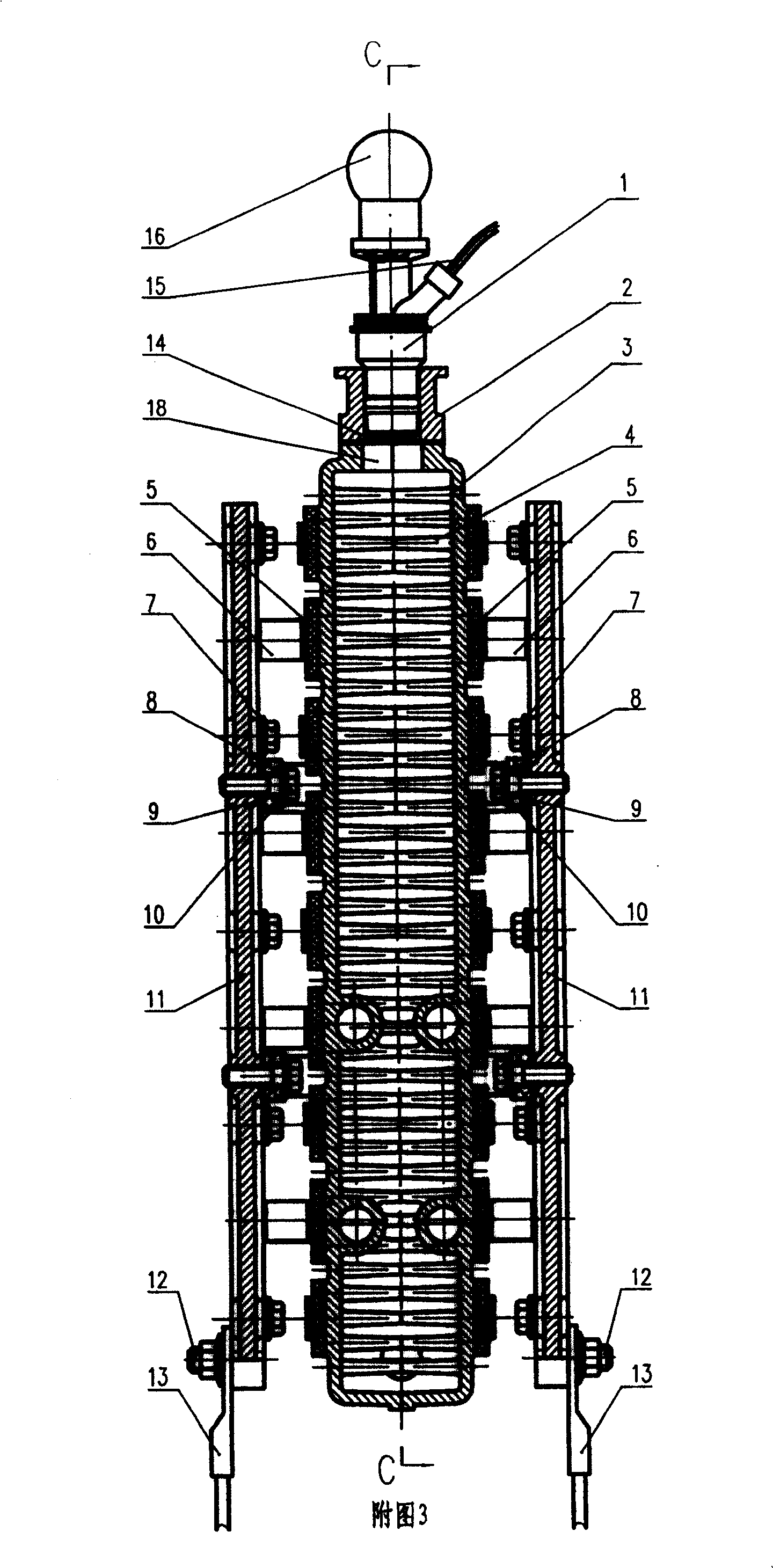
This invention relates to a fuel-supply device for methanol engines. The constant-temperature-heating methanol reforming system comprises an electrically controlled methanol nozzle, a reforming chamber, and multiple reforming columns in the reforming chamber. Catalyst layers are set on the surface of the reforming columns as well as the inner wall of the reforming chamber for promoting methanol reforming. A PTC constant-temperature-heating element is set out of the reforming chamber, and connected with one end of a spring leaf. The other end of the spring leaf is connected with an electrode, which is fixed on the reforming chamber by an insulating block. This invention solves the problems of the difficulty of methanol cold-start as well as the emission of harmful formaldehyde intermediate during methanol combustion. In this invention, methanol is firstly introduced into the constant-temperature-heating reforming system to generate H2 and CO, which are then supplied to the engines for combustion. This invention thus has such advantages as no formaldehyde emission, better cold-start performance and little exhause pollution.
Description
technical field [0001] The invention relates to a fuel supply device for a methanol engine, in particular to a catalyst heated by a constant temperature heating element to decompose and reform methanol to feed liquid methanol (CH 3 OH) reformed into hydrogen (H 2 ) and carbon monoxide (CO) gas fuel constant temperature heating methanol decomposition reforming device. Background technique [0002] Most of the automobile engines in the prior art use gasoline or diesel as fuel. With the increasing shortage of oil resources and stricter automobile emission regulations, countries all over the world are looking for various alternative fuels for gasoline and diesel, among which methanol is a better alternative fuel. . Methanol can be produced from coal, natural gas and wood, and the use of methanol as engine fuel can ensure my country's long-term energy security. At present, there are problems such as difficulty in cold starting of engines fueled with methanol, and harmful forma...
Claims
Login to View More Application Information
Patent Timeline
 Patent Type & AuthorityPatents(China)
IPC IPC(8): C01B3/22
Inventor郑国璋朱建军王淑平郭建玲靳红玲
Owner郑国璋