Mixed flow type water turbin having H-type flow path rotary wheel

A water turbine and mixed-flow technology, applied in the field of fluid machinery and engineering equipment, can solve the problems of unit safety operation hazards, water turbine efficiency reduction, water turbine operation restrictions, etc., to expand high-efficiency operation area, improve flow conditions, and simple structure Effect

Inactive Publication Date: 2008-10-22
TSINGHUA UNIV
View PDF6 Cites 0 Cited by
  • Summary
  • Abstract
  • Description
  • Claims
  • Application Information

AI Technical Summary

Problems solved by technology

As a result, the flow is unstable, the efficiency of the turbine is reduced, the hydraulic vibration is increased, and the operation of the turbine is limited, which brings great harm to the safe operation of the unit.

Method used


Image

  • Mixed flow type water turbin having H-type flow path rotary wheel
  • Mixed flow type water turbin having H-type flow path rotary wheel
  • Mixed flow type water turbin having H-type flow path rotary wheel

Examples


Embodiment Construction

[0014] The principle and structure of the present invention will be further described below in conjunction with the accompanying drawings.

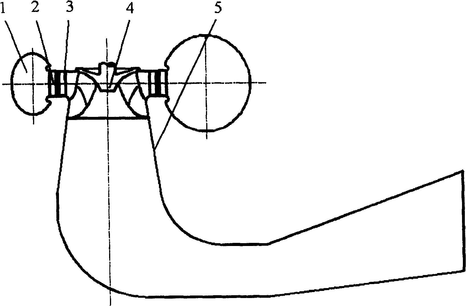
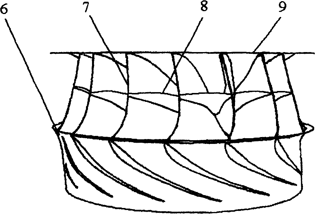
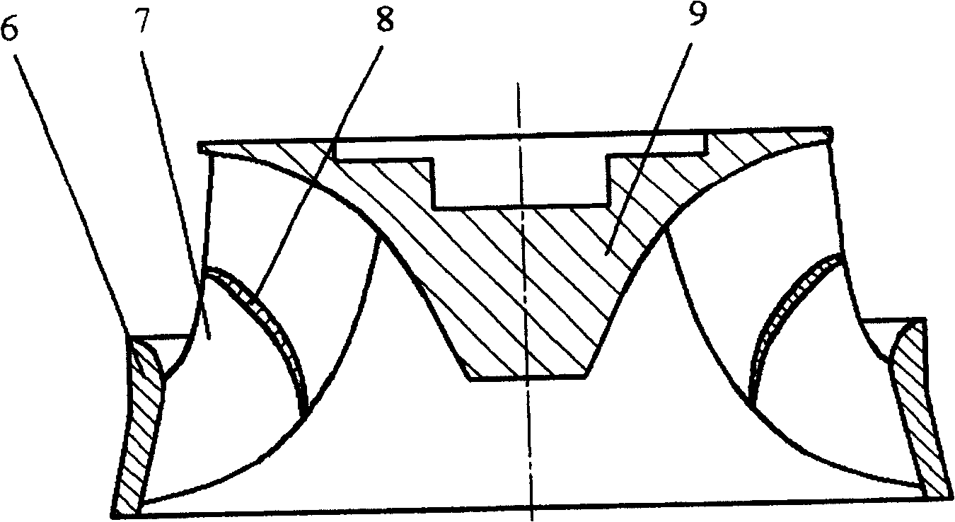
[0015] figure 1 It is a schematic structural diagram of the Francis turbine of the H-type channel runner provided by the present invention. The Francis turbine includes a volute 1, a fixed guide vane 2, a movable guide vane 3, an H-shaped runner 4 and a draft tube 5 according to the direction of water flow; the H-shaped runner 4 consists of an upper crown 9, a lower ring 6. The rotor blades 7 fixed between the upper crown and the lower ring and the guide vanes 8 are formed, and the guide vanes 8 are installed between every two adjacent runner blades 7 (such as figure 2 , image 3 As shown), an H-shaped flow channel is formed; the guide vane 8 is placed in the middle of the flow channel, and the length is the same as that of the runner blade. The streamline in the middle of the flow channel under the optimal working condition is the bon...


PUM


Abstract

A flow-mixed turbine features that a flow guiding blade which has the length equal to that of the blade on rotary wheel and the maximal thickness equal to the 2 / 3-1 / 2 of that of the blade on rotary wheel is transversely added between two blades on rotary wheel to form a H-shaped flow channel for preventing transverse flow, resulting in higher efficiency and low hydraulic vibration.

Description

technical field [0001] The invention relates to a Francis water turbine, in particular to a Francis water turbine with an H-shaped channel runner, belonging to the technical field of fluid machinery and engineering equipment. Background technique [0002] The Francis turbine is currently the most widely used water turbine. The water flows radially into the runner blades, pushes the runner to do work, and changes the flow direction to flow out axially. Francis turbines are generally suitable for water heads ranging from 50 to 700 meters, and outputs ranging from tens of thousands of kilowatts to several million kilowatts. [0003] The Francis turbine is a fixed blade turbine, and the blades are fixed between the upper crown and the lower ring. When the Francis turbine operates in a deviation from the design condition, impact will occur at the blade inlet of the runner, and the blade outlet will form an outlet with a ring. Especially in the case of small flow rate, a wide ran...

Claims


Application Information

Patent Timeline
Patent Type & Authority Patents(China)
IPC IPC(8): F03B3/12F03B3/02
CPCY02E10/223Y02E10/20
Inventor 张梁刘树红罗先武吴玉林
Owner TSINGHUA UNIV
Why Eureka
Try Eureka