High-blocking-ratio fin layer plate cooling structure and method for turbine blade mid-chord area

A technology for turbine blades and cooling structures, which is applied to blade support components, machines/engines, mechanical equipment, etc., can solve the problems of large compressor power loss and pressure loss, and achieve increased air intake, reduced pressure loss, and suppression of cross flow Effect

Pending Publication Date: 2022-04-22
NORTHWESTERN POLYTECHNICAL UNIV
View PDF0 Cites 2 Cited by
  • Summary
  • Abstract
  • Description
  • Claims
  • Application Information

AI Technical Summary

Problems solved by technology

Existing literature studies have shown that fins with a high plugging ratio can effectively weaken the impact of cross flow on impingement heat transfer and enhance the overall heat transfer characteristics, but at the same time cause more pressure loss (flow resistance), The cold air in the turbine blades is usually provided by the compressor, the greater the resistance of the cold air flowing through the cooling unit, the greater the power loss of the compressor

Method used


Image

  • High-blocking-ratio fin layer plate cooling structure and method for turbine blade mid-chord area
  • High-blocking-ratio fin layer plate cooling structure and method for turbine blade mid-chord area
  • High-blocking-ratio fin layer plate cooling structure and method for turbine blade mid-chord area

Examples


Embodiment 1

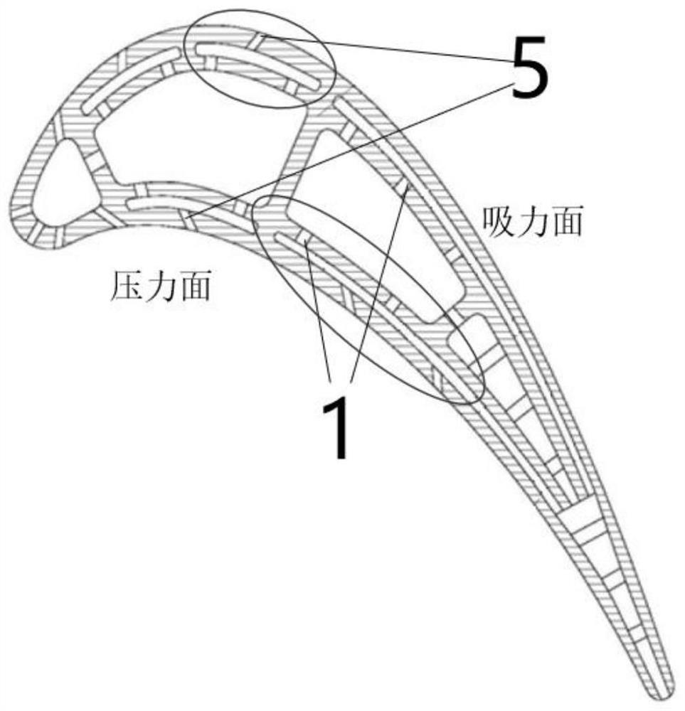
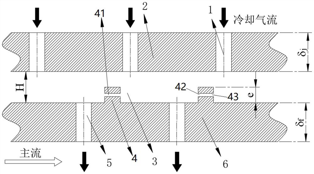
[0039] Embodiment 1: as Figure 1-4 , Figure 10 Shown, a kind of turbine blade middle chord region uses the cooling structure of the high clogging ratio rib laminate, comprises the blade double wall that is positioned at blade mid chord, and described blade double wall is made of air film orifice plate 6 and impingement orifice plate 2, and the impingement air flow cooling passage 3 between the air film orifice plate 6 and the impact orifice plate 2; the impact orifice plate 2 is an air inlet plate, which is arranged on the cold air side of the turbine blade; the air film orifice plate 6 is an air outlet plate The air film orifice plate 6 is arranged on the gas side of the turbine blade; the impact orifice plate 2 and the air film orifice plate 6 both have a thickness of 0.5-3d and a spanwise width of 4-8d.

[0040]On described air film orifice plate 6, be provided with air film hole 5 evenly and equidistantly, be provided with impact hole 1 evenly and equidistantly on descr...

Embodiment 2

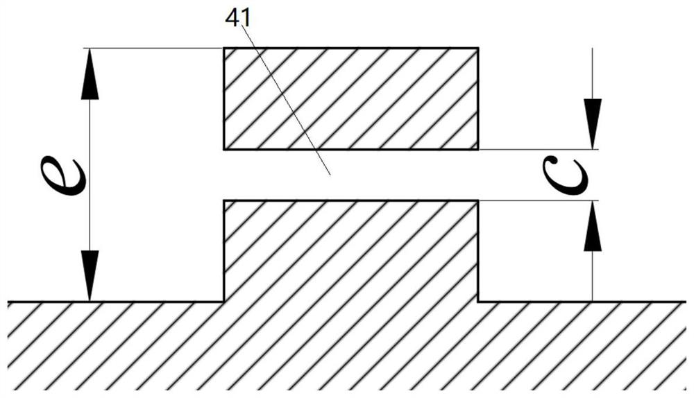
[0045] Embodiment 2: as Figure 6-8 As shown, the parallel slits 41 are arranged obliquely relative to the flow direction of the airflow, the inclination angle α is 0-30°, and the penetration rate β=c / e is 0.05-0.4, wherein c is the ratio of the parallel slits 41 Height, e is the height of the fin 4 with high blockage ratio.

Embodiment 3

[0046] Embodiment 3: as Figure 5 As shown, the present invention also provides the cooling method of the high clogging ratio fin laminate cooling structure for the midchord region of the turbine blade described in Embodiment 1, comprising the following steps:

[0047] The cooling air flow passes through the impact hole 1 to perform impact heat exchange on the inner wall surface of the air film orifice plate 6, and the cooling air flow impacting the air film orifice plate 6 diffuses to form a wall jet A, and then forms a cross flow B along the direction of the cold air flow; at this time, The high blockage ratio fins 4 play a role in strengthening the turbulence of the cooling air flow, and the upwardly deflected wall jet A1 generated in the upstream area of ​​the impingement hole 1 is separated from the downward flow jet A1 separated from the upper surface of the adjacent high blockage ratio fins 4 . The cooling air flow A2 is mixed, and a small recirculation zone A3 is gener...


PUM


Abstract

The high-blocking-ratio fin layer plate cooling structure for the turbine blade mid-chord area comprises a blade double-layer wall located on a blade mid-chord, and the blade double-layer wall is composed of an air film hole plate, an impact hole plate and an impact airflow cooling channel between the air film hole plate and the impact hole plate. A high-blocking-ratio fin is arranged on the portion, in the impact airflow cooling channel, of the air film hole plate in the blade height direction of the turbine blade in an extending mode, and parallel slits used for disturbing and reducing the flow resistance of cooling air are formed in the high-blocking-ratio fin in the cooling airflow direction. The parallel gaps in the middle of the fins reduce the flow resistance of the structure and reduce the pressure loss, the air entraining amount is not increased while the heat exchange effect is enhanced, meanwhile, due to the fact that disturbance of cooling airflow is enhanced through the fins, convective heat exchange between fluid and solid in the double-layer wall is enhanced, and after the fins are arranged, the total heat transfer amount is correspondingly increased.

Description

technical field [0001] The present invention relates to blade cooling structures, and in particular to internal cooling structures in the midchord region of turbine blades. Background technique [0002] Aeroengine / gas turbine power and efficiency increase with increasing turbine inlet gas temperature. The turbine inlet temperature of gas turbine engines currently in service has exceeded 1850K, far exceeding the heat resistance limit of blade superalloy materials (1150K), and the turbine inlet temperature of advanced gas turbine engines is showing a rising trend. Therefore, in order to To ensure the safe and reliable operation of turbine blades under high heat load conditions, efficient cooling measures must be taken. [0003] The impingement-film double wall cooling technology has attracted the attention of many researchers because it fully combines the advantages of internal impingement cooling and external film cooling. In the impact / air film double-wall film cooling str...

Claims


Application Information

Patent Timeline
Patent Type & Authority Applications(China)
IPC IPC(8): F01D5/18
CPCF01D5/186F01D5/188
Inventor 孔德海马振源李维李洋刘存良
Owner NORTHWESTERN POLYTECHNICAL UNIV
Why Eureka
Try Eureka