Cooling structure with slit rib laminates for turbofan engine combustion chamber and cooling method

A turbofan engine and cooling structure technology, applied in the cooling of the engine, engine components, turbine/propulsion device, etc., can solve the problems of weakening the influence of cross flow, high temperature gradient thermal failure, uneven heat flux distribution on the inner wall of the engine, etc.

Active Publication Date: 2022-04-29
NORTHWESTERN POLYTECHNICAL UNIV
View PDF11 Cites 0 Cited by
  • Summary
  • Abstract
  • Description
  • Claims
  • Application Information

AI Technical Summary

Problems solved by technology

[0005]Existing literature studies have shown that fins with high plugging ratio can effectively weaken the impact of cross flow on impingement heat transfer and enhance the overall heat transfer characteristics, but It can also lead to non-uniform heat flux distribution on the inner walls of high bypass ratio engines, leading to localized high temperature gradients and thermal failures

Method used


Image

  • Cooling structure with slit rib laminates for turbofan engine combustion chamber and cooling method
  • Cooling structure with slit rib laminates for turbofan engine combustion chamber and cooling method
  • Cooling structure with slit rib laminates for turbofan engine combustion chamber and cooling method

Examples


Embodiment 1

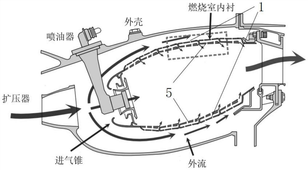
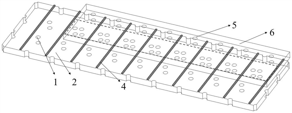
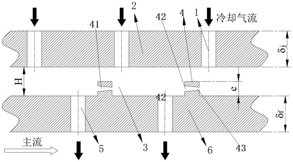
[0047] Embodiment 1: as Figure 1-4 Shown, a kind of turbofan engine combustor cooling structure with slit-ribbed laminates comprises a gas-film orifice plate 6 and an impact orifice plate 2, and the impact orifice plate 2 and the gas-film orifice plate 6 are arranged in parallel. An impingement air flow cooling passage 3 is arranged between the film orifice plate 6 and the impingement orifice plate 2, and the air film orifice plate 6, the impingement orifice plate 2 and the impingement air flow cooling passage 3 constitute the combustion chamber lining of the turbofan engine. wall structure;

[0048] On the surface of the air film orifice plate 6 located in the impingement airflow cooling channel 3, a plurality of high blockage ratio annular fins 4 are arranged along the airflow direction, and the plurality of high blockage ratio annular fins 4 are parallel to each other, and are cooled along the airflow direction. At least two contraction or expansion slits 41 for improving...

Embodiment 2

[0056] Embodiment 2: as Figure 5 As shown, a kind of cooling method that the present invention provides is as embodiment 1 turbofan engine combustor cooling structure with slit ribs, comprising the following steps:

[0057] The cooling air flow passes through the impact hole 1 to perform impact heat exchange on the inner wall surface of the air film orifice plate 6, and the cooling air flow impacting the air film orifice plate 6 diffuses to form a wall jet A, and then forms a cross flow B along the direction of the cold air flow; at this time, The high blocking ratio annular fin 4 blocks the cooling air flow, and the cross flow B interacts with the descending separated flow C formed on the upper surface of the high blocking ratio annular fin 4 to form a large recirculation zone D;

[0058] Part of the cooling airflow in the impingement airflow cooling channel 3 is ejected from the shrinking slit and interacts with the large recirculation area D, forming a first angular vortex...

Embodiment 3

[0060] Embodiment 3: as Figure 6-7 As shown, it is the same as the embodiment 1, except that the contraction or expansion slit 41 is an expansion slit, and the height of the slit entrance 42 of the expansion slit is lower than the height of the slit exit 43 .


PUM


Abstract

The invention relates to a rib layer plate cooling structure with slits for a combustion chamber of a turbofan engine, which is characterized in that a plurality of high-blockage-ratio annular ribs are arranged on the surface, positioned in an impact airflow cooling channel, of an air film pore plate along the airflow direction, and the plurality of high-blockage-ratio annular ribs are parallel to one another; at least two contraction or expansion slits used for improving heat exchange uniformity are formed in the high-blocking-ratio annular fin in the cooling airflow direction, and the at least two contraction or expansion slits are formed in the high-blocking-ratio annular fin at intervals. After the contraction/expansion type slit ribs are arranged on the wall surface of the impact target plate, the heat transfer performance of a low heat transfer area between impact jet flow areas on the impact target plate in traditional impact cooling is improved, so that the heat transfer uniformity of the wall surface of the impact target plate is improved.

Description

technical field [0001] The invention relates to an engine cooling structure, in particular to a cooling structure for a combustion chamber of a turbofan engine with a high bypass ratio. Background technique [0002] The aero-engine has developed from the second generation to the fourth generation, and the wall temperature of the combustion chamber has increased by 300°C per generation. The increase in temperature has brought more severe challenges to the structural design and working stability of the aero-engine combustion chamber. In a turbofan engine, the combustion chamber is a key component that determines the life and reliability of the turbofan engine, and they are directly impacted by high-temperature gas during operation. Seeking the development of high-temperature-resistant alloy materials and adopting more efficient cooling technology are two trends in the future research on the stability of aero-engines. At present, the development of high-temperature-resistant al...

Claims


Application Information

Patent Timeline
Patent Type & Authority Applications(China)
IPC IPC(8): F02C7/18
CPCF02C7/18
Inventor 孔德海马振源李维李洋刘存良
Owner NORTHWESTERN POLYTECHNICAL UNIV
Why Eureka
Try Eureka