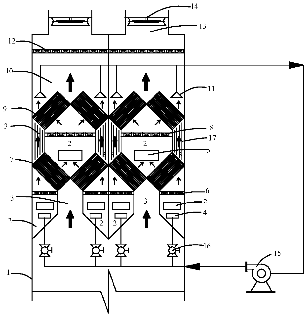
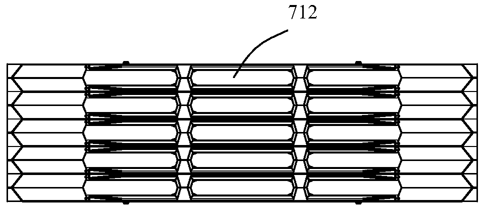
Anti-freezing saturated wet tail gas condensation dehumidification device and method

A technology for exhaust gas and moisture, applied in chemical instruments and methods, separation methods, gas treatment, etc., can solve the problems of high operation cost, high energy consumption of reheating and dehumidification process, and difficulty in realizing flue gas dehumidification and fog elimination. The effect of exhausting smoke and white mist, improving the stability of winter operation and preventing freezing

Pending Publication Date: 2020-08-14
新疆天富环保科技有限公司
View PDF0 Cites 0 Cited by
  • Summary
  • Abstract
  • Description
  • Claims
  • Application Information

AI Technical Summary

Problems solved by technology

[0003] There are two types of dehumidification for industrial saturated wet flue gas: reheat dehumidification and condensation dehumidification: the reheat dehumidification process increases the temperature of the saturated wet flue gas by increasing the heat source, thereby reducing the relative humidity of the exhaust gas, realizing the dehumidification of the flue gas discharge, and reheating The dehumidification process consumes a lot of energy and has high operating costs. In winter, due to the low ambient temperature, it is difficult to achieve dehumidification and fog removal of flue gas. Moisture in the gas, so as to achieve flue gas dehumidification emission

Method used


Image

  • Anti-freezing saturated wet tail gas condensation dehumidification device and method
  • Anti-freezing saturated wet tail gas condensation dehumidification device and method
  • Anti-freezing saturated wet tail gas condensation dehumidification device and method

Examples


Embodiment Construction

[0059] The following will clearly and completely describe the technical solutions in the embodiments of the application with reference to the drawings in the embodiments of the application. Apparently, the described embodiments are only some of the embodiments of the application, not all of them. Based on the embodiments in this application, all other embodiments obtained by persons of ordinary skill in the art without making creative efforts belong to the scope of protection of this application.

[0060] In order to better describe and illustrate the embodiments of the application, reference may be made to one or more drawings, but additional details or examples used to describe the drawings should not be regarded as an invention of the application, the presently described implementation limitations on the scope of any of the examples or preferred modes.

[0061] It should be noted that when a component is said to be "connected" to another component, it may be directly connec...


PUM


Abstract

The invention discloses an anti-freezing saturated wet tail gas condensation dehumidification device and method. The device comprises a dehumidification tower and an anti-freezing assembly. The dehumidification tower comprises a tower body, a moisture inlet is formed in the bottom or side wall of the tower body, an exhaust port is formed in the top, dehumidification layers are arranged in the tower body and located above the moisture inlet layer by layer in the smoke flow direction, a plurality of heat exchange modules are arranged in each dehumidification layer, each heat exchange module comprises a plurality of heat exchange membranes which are bonded in sequence, a hot flow channel and a cold flow channel which are distributed by the heat exchange membranes at intervals and are vertically communicated with each other are formed in the heat exchange module, the anti-freezing assembly comprises a preheating air collecting cover and a preheating fan, the preheating air collecting coveris located in the space above the top dehumidification layer, an air inlet of the preheating fan is connected with the preheating air collecting cover through a pipeline, and an air outlet of the preheating fan is connected to the position below a cold flow channel inlet of the heat exchange module in the bottom dehumidification layer through a pipeline. Water resources in the high-humidity fluegas can be effectively recycled, the phenomenon that the high-humidity flue gas discharges white mist is eliminated, and the operation stability of the dehumidification system in winter can be improved.

Description

technical field [0001] The application relates to the field of resource and environmental protection, and in particular to an antifreeze-type saturated wet tail gas condensation dehumidification device and method. Background technique [0002] There are a large number of evaporation, drying, and heat exchange processes in the industrial production process, and a large amount of saturated or supersaturated high-humidity tail gas and steam need to be discharged into the environment. Industrial high-humidity tail gas emission sources are widely distributed, covering different production stages of electric power, drying, printing and dyeing, ceramics, petroleum, chemical, pharmaceutical and other industries, with many emission points, low emission height, high tail gas humidity and large emission and other characteristics; the temperature of the exhaust gas is generally 45°C-100°C, and the relative humidity of the exhaust gas is about 100%. The high-humidity flue gas is dischar...

Claims


Application Information

Patent Timeline
Patent Type & Authority Applications(China)
IPC IPC(8): B01D53/26
CPCB01D53/265B01D2257/80
Inventor 杨志国蒋红孙陟潘浩秦乐陈晓雨摆玉芬曲欣李红跃朱磊张益玮巴荣李丹
Owner 新疆天富环保科技有限公司
Why Eureka
Try Eureka