
Intake temperature control system to meet intake temperature requirement of gasoline compression ignition full conditions

A technology of intake air temperature and control system, which is applied in the direction of combustion air/combustion-air treatment, charging system, fuel heat treatment device, etc., and can solve problems such as small load combustion instability, low fuel activity, and long combustion delay period , to achieve the effect of improving combustion stability, combustion efficiency and utilization rate

Active Publication Date: 2019-01-22
TIANJIN UNIV
View PDF6 Cites 3 Cited by
  • Summary
  • Abstract
  • Description
  • Claims
  • Application Information

AI Technical Summary

Problems solved by technology

[0004] With the deepening of research, scholars have found that due to the high octane number of gasoline fuel, the fuel activity is too low, the ignition performance is poor, and the ignition delay period is long, so that gasoline compression ignition (GCI) has problems such as cold start difficulty and small-load combustion instability. ; And at high load, due to the increase of fuel-air equivalence ratio, gasoline compression ignition (GCI) has the problem of premature combustion

Method used


Image

  • Intake temperature control system to meet intake temperature requirement of gasoline compression ignition full conditions
  • Intake temperature control system to meet intake temperature requirement of gasoline compression ignition full conditions

Examples


Embodiment Construction

[0020] The technical solutions of the present invention will be described in further detail below with reference to the accompanying drawings and specific embodiments, and the described specific embodiments are only used to explain the present invention, and are not intended to limit the present invention.

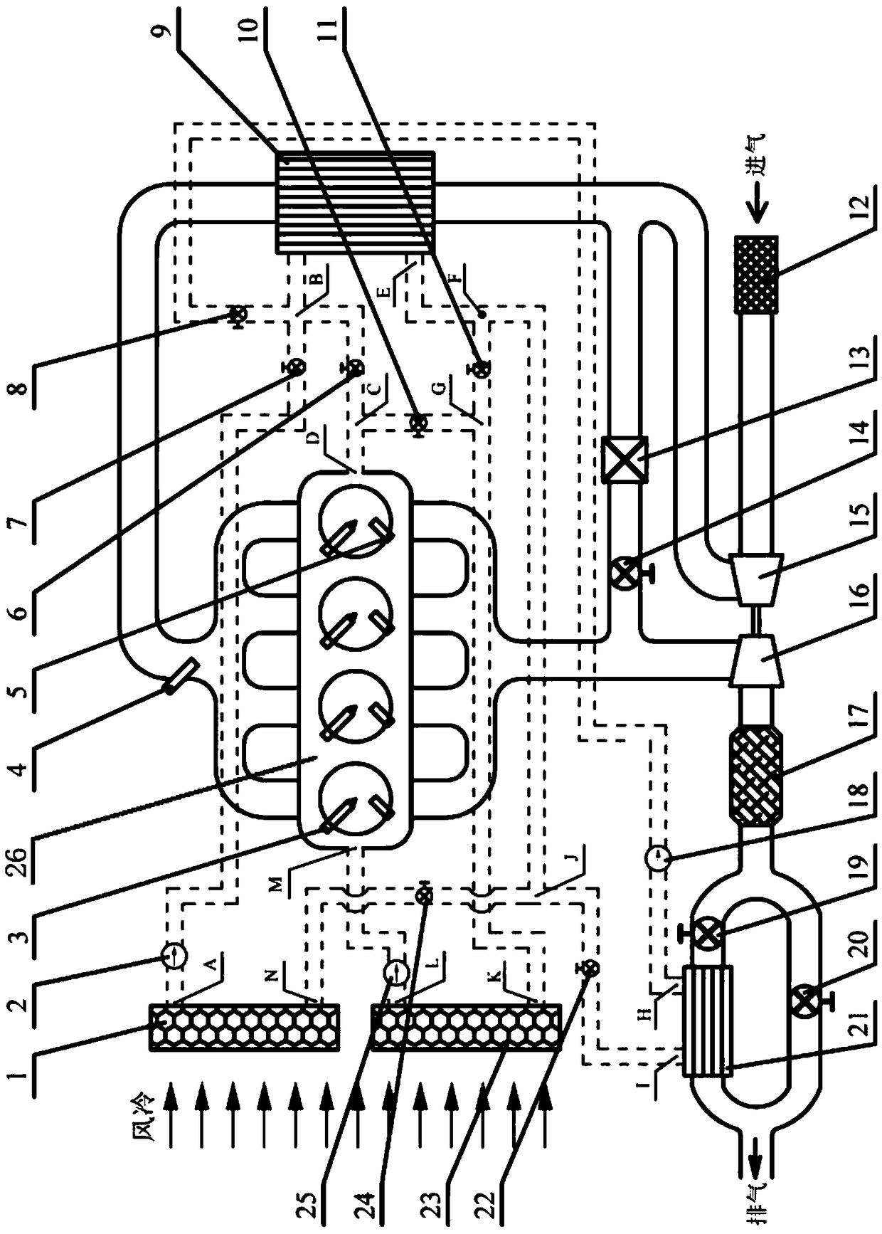
[0021] like figure 1 As shown in the figure, the intake air temperature control system of the present invention that satisfies the intake air temperature requirements under all gasoline compression ignition conditions includes a dual variable valve mechanism 26 arranged in the compression ignition engine. A fuel injector 3 and a glow plug 5 are arranged in each cylinder. Each cylinder intake port of the dual variable valve mechanism 26 is connected to an intake manifold, all intake manifolds are connected to an intake manifold outlet, and the intake manifold intake port is connected to the exhaust of the compressor 15 The air inlet of the compressor 15 is connected to the...


PUM


Abstract

The invention discloses an intake temperature control system to meet intake temperature requirement of gasoline compression ignition full conditions. An intake port of a dual-variable-valve mechanismis connected with an intake master tube that is connected with a gas compressor; an exhaust port of the dual-variable-valve mechanism is connected with an exhaust master tube; the exhaust master tubeis connected with a turbine that is connected with a post-processor; the intake master tube is provided with an intercooler; an exhaust port of the post-processor is connected with two exhaust branches; one exhaust branch is provided with a second exhaust valve, and the other exhaust branch is provided with a first exhaust valve and an exhaust heat exchanger; a shell side water outlet of the exhaust heat exchanger is connected with a shell side water inlet of the intercooler; a shell side water inlet of the exhaust heat exchanger is connected with a shell side water outlet of the intercooler;the shell side water inlet of the intercooler is connected with a water inlet of a first radiator; the shell side water outlet of the intercooler is connected with a water inlet of the first radiator;the shell side water outlet of the intercooler is connected with a water inlet of the second radiator; the shell side water inlet of the intercooler is connected with a water outlet of a cooling water passage of an engine; a water outlet of the second radiator is connected with a water inlet of the cooling water passage of the engine.

Description

technical field [0001] The invention relates to the field of internal combustion engines, and more particularly, to an intake air temperature control system that meets the requirements for intake air temperature in all operating conditions of gasoline compression ignition. Background technique [0002] The automobile industry is a pillar industry of the national economy, but with the increasing number of automobiles, the problems of environmental pollution and energy shortage caused by automobiles have increasingly attracted the attention of governments of various countries. In order to cope with the increasingly severe energy and environmental problems, countries have formulated more stringent regulations on harmful emissions and fuel economy, thus posing new challenges to the efficient and clean combustion control technology of internal combustion engines. [0003] As a conventional fossil fuel, gasoline is widely used in spark-ignition gasoline engines. However, the igni...

Claims


Application Information

Patent Timeline
IPC IPC(8): F02M31/087F02M31/10F02M31/20F02B29/04
CPCF02B29/04F02M31/087F02M31/10F02M31/205Y02T10/12
Inventor 尧命发刘佳林郑尊清王浒张弟平
Owner TIANJIN UNIV
Learn More