
Exhaust waste heat utilization system of gas turbine heat channel cooling air heat exchanger

A technology for gas turbine and cooling air, which is applied in the direction of gas turbine device, cooling of engine, cooling of turbine/propulsion device, etc., can solve problems such as environmental thermal pollution and energy waste, and achieve the effect of improving operating economy

Pending Publication Date: 2021-02-12
HUANENG POWER INT INC +2
View PDF0 Cites 2 Cited by
  • Summary
  • Abstract
  • Description
  • Claims
  • Application Information

AI Technical Summary

Problems solved by technology

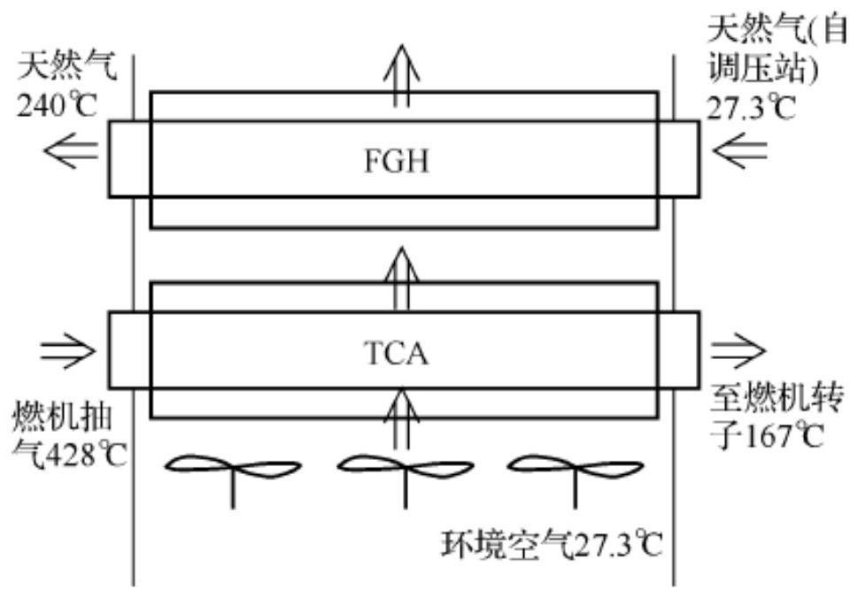
In the gas turbine hot aisle cooling air heat exchanger, the fan sucks in cold air, and the cold air convects and exchanges heat with the compressor air in the TCA heat exchanger (compressed air heat exchanger) to become hot air, and the hot air is further exchanged with the FGH The cold natural gas in the heat exchanger (natural gas heat exchanger) is discharged into the atmosphere after convective heat exchange. Generally, the natural gas in the FGH heat exchanger can only recover about 60% of the heat released by the compressor in the TCA heat exchanger. The hot aisle cooling air heat exchanger will still discharge a large amount of high-temperature air to the atmosphere (under design conditions, the temperature of the high-temperature air discharged directly exceeds 160°C and the heat exceeds 4MW), resulting in energy waste and environmental heat pollution
[0006] At present, there is no energy-saving system with a reasonable design, which can not only use the heat passage of the gas turbine to cool the exhaust waste heat of the air heat exchanger, but also improve the operating economy of the combined cycle unit under part load conditions.

Method used


Image

  • Exhaust waste heat utilization system of gas turbine heat channel cooling air heat exchanger
  • Exhaust waste heat utilization system of gas turbine heat channel cooling air heat exchanger
  • Exhaust waste heat utilization system of gas turbine heat channel cooling air heat exchanger

Examples


Embodiment Construction

[0028] The present invention will be described in detail below in conjunction with accompanying drawing and embodiment:

[0029] Such as Figure 4 As shown, a gas turbine hot passage cooling air heat exchanger exhaust waste heat utilization system provided by the present invention includes: a compressor intake passage 1, a gas turbine, a waste heat boiler and a steam turbine system 5, a gas turbine hot passage cooling air heat exchanger, The first air passage 10, the second air passage 11, the first air flow regulating valve 101, the second air flow regulating valve 102, and the compressor inlet temperature measurement system 103; the gas turbine includes a compressor 2 and a combustion chamber 3 connected in sequence and gas turbine 4; the gas turbine hot passage cooling air heat exchanger includes a fan group 6 connected in sequence, a compressed air heat exchanger 7 and a natural gas heat exchanger 8, and a heat exchanger housing 9 containing the above components .

[003...


PUM


Abstract

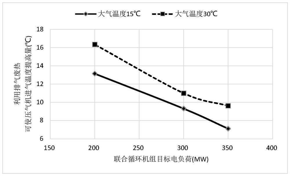
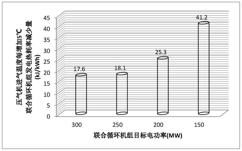
The invention discloses an exhaust waste heat utilization system of a gas turbine heat channel cooling air heat exchanger. The exhaust waste heat utilization system mainly comprises a gas compressor gas inlet channel, a gas turbine, a waste heat boiler, a steam turbine, the gas turbine heat channel cooling air heat exchanger and an air channel. According to the exhaust waste heat utilization system, high-temperature exhaust energy of the gas turbine heat channel cooling air heat exchanger which is originally directly exhausted to the atmosphere is used for heating gas compressor inlet gas, thegas compressor inlet gas temperature is increased, the load rate of a combined cycle unit under the partial load working condition is increased, then the power generation efficiency of the combined cycle unit is improved, and the beneficial effect of improving the running economy of the combined cycle unit under the partial load working condition is achieved.

Description

technical field [0001] The invention belongs to the technical field of energy utilization, and in particular relates to a gas turbine hot channel cooling air heat exchanger exhaust waste heat utilization system. Background technique [0002] my country's combined cycle units generally undertake the peak-shaving function of the power grid and operate under partial load conditions for a long time. Under the current downward pressure on the national economy, less equipment utilization hours and low operating load rates have become the new normal operation of combined cycle units. [0003] Compared with the base load condition, the operating economy of the combined cycle unit under the partial load operation condition will be severely reduced. Generally speaking, for the mainstream F-class combined cycle unit, every time the operating load rate is reduced by 10%, the average gross power generation heat rate of the unit will decrease. The increase is about 200-300kJ / kWh, which le...

Claims


Application Information

Patent Timeline
Patent Type & Authority Applications(China)
IPC IPC(8): F02C7/08F02C7/18F02C7/224
CPCF02C7/08F02C7/18F02C7/224
Inventor 肖俊峰吴昌兵周刚胡孟起夏林向东高松张学华王科连小龙赵思勇葛晓明刘印
Owner HUANENG POWER INT INC
Learn More