Tee joint material fluidistor of improved structure

A technology of fluidizer and tee, which is applied in the direction of conveying bulk materials, conveyors, transportation and packaging, etc. It can solve the problems of low feeding efficiency, poor fluidization degree, blockage of intake pipe, etc., and improve feeding efficiency , reduce the failure rate, improve the effect of intake air temperature

Active Publication Date: 2015-07-08
TIANJIN SHIDA ELECTRIC POWER EQUIP
View PDF8 Cites 2 Cited by
  • Summary
  • Abstract
  • Description
  • Claims
  • Application Information

AI Technical Summary

Problems solved by technology

[0004] In order to solve the above technical problems, the present invention provides a three-way material fluidizer with an improved structure to solve the problems of low feed efficiency, poor fluidization degree, and prone to blockage of the intake pipe in the existing fluidizer.

Method used


Image

  • Tee joint material fluidistor of improved structure
  • Tee joint material fluidistor of improved structure
  • Tee joint material fluidistor of improved structure

Examples


Embodiment

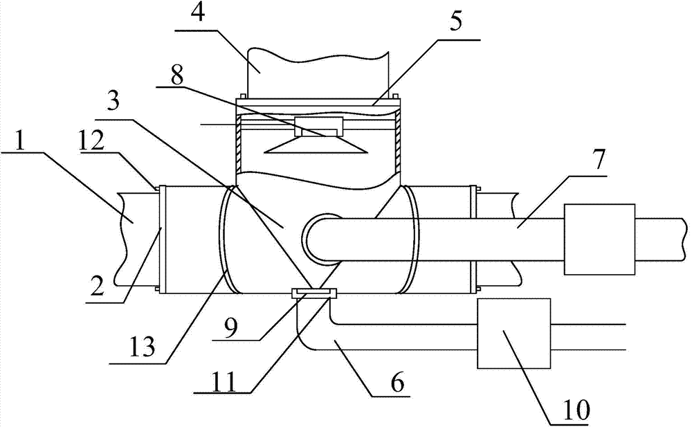
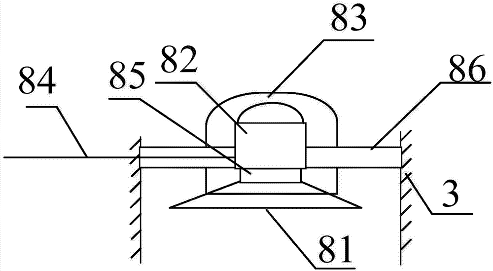
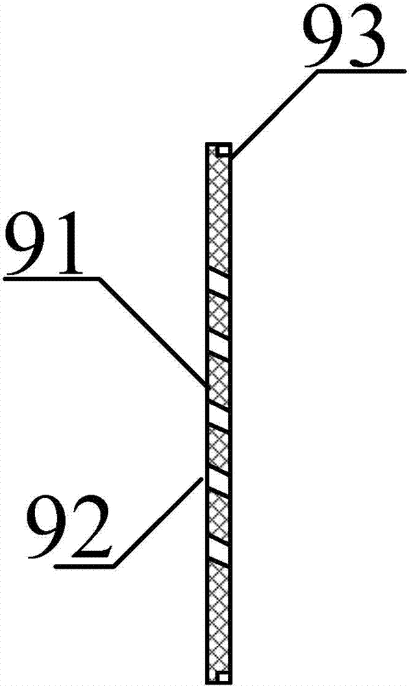
[0024] as attached figure 1 To attach Figure 4 shown

[0025] The invention provides a three-way material fluidizer with an improved structure, which includes a side discharge port 1, a discharge flange 2, a tee body 3, a top feed port 4, a feed flange 5, and a bottom inlet pipe 6. Side air intake pipe 7, vibrating device 8, cut-off plate 9, preheating device 10, air pipe joint 11, fixing bolt 12 and protective plate 13, the side discharge port 1 is installed on the three-way body through the discharge flange 2 The left and right sides of 3; the top feed inlet 4 is installed on the top of the tee body 3 through the feed flange 5; the bottom air intake pipe 6 is installed on the lower side of the tee body 3 through the air pipe joint 11; The side intake pipe 7 is installed on the front and rear sides of the tee body 3 through the air pipe joint 11; the vibration device 8 is installed at the bottom of the top feed port 4; the cut-off plate 9 is embedded in the inner side of t...


PUM


Abstract

The invention provides a tee joint material fluidistor of an improvd structure. The fluidistor comprises side discharge ports, discharge flanges, a tee joint body, a top feed port, a feed flange, a bottom air inlet pipe, a side air inlet pipe, a vibration device, an intercepter plate, a preheating device, an air pipe joint, a fixed bolt and a protection plate, and the side discharge ports are installed at the left side and the right side of the tee joint body through the discharge flanges; the top feed port is installed on the upper portion of the tee joint body through the feed flange; the bottom air inlet pipe is installed at the lower side of the tee joint body through the air pipe joint. According to the fluidistor, through the arrangements of the vibration device, the preheating device, the intercepter plate and the protection plate, it is facilitated to improve the feeding efficiency, the fluidization degree is improved, the failure rate is reduced, and the market application and popularization are facilitated.

Description

technical field [0001] The invention belongs to the technical field of material fluidization, in particular to a three-way material fluidizer with an improved structure. Background technique [0002] At present, due to the use of coal with poor coal quality in the supply of electric coal, the ash quality is getting worse and worse, making many original good material conveying systems unable to operate normally. Customers are very eager for the birth of a new type of high-efficiency material fluidizer. To ensure the safe and stable operation of the system, the research on high-efficiency material fluidizers is particularly important. The current technology has a Chinese patent publication number of CN 204100559 U. The name of the invention is a high-efficiency material fluidizer, which includes a side air intake pipe, a bottom air intake pipe and a fluidization tee. The side air intake pipe is mirror-symmetrically installed on the fluidization tee. The left and right sides o...

Claims


Application Information

Patent Timeline
Patent Type & Authority Applications(China)
IPC IPC(8): B65G53/34B65G53/56
Inventor 黄申郭富强王宝国
Owner TIANJIN SHIDA ELECTRIC POWER EQUIP
Why Eureka
Try Eureka