Compressor

A technology of a compressor and a compression mechanism, applied in the field of compressors, can solve the problems of reduced compressor efficiency and increased gas pressure loss, etc.

Inactive Publication Date: 2008-10-22
DAIKIN IND LTD
View PDF9 Cites 1 Cited by
  • Summary
  • Abstract
  • Description
  • Claims
  • Application Information

AI Technical Summary

Problems solved by technology

[0006] However, if the structure like the above-mentioned Patent Document 1 is adopted, there is a problem that the efficiency of the compressor is lowered.
That is, in the compressor of Patent Document 1, since the gas flows to the compression mechanism through the curved suction passage, the pressure loss of the gas until it reaches the compression chamber becomes large.
Therefore, the gas density at the moment of flowing into the compression chamber decreases, and as a result, the efficiency of the compressor decreases.

Method used


Image

  • Compressor
  • Compressor
  • Compressor

Examples


no. 1 Embodiment

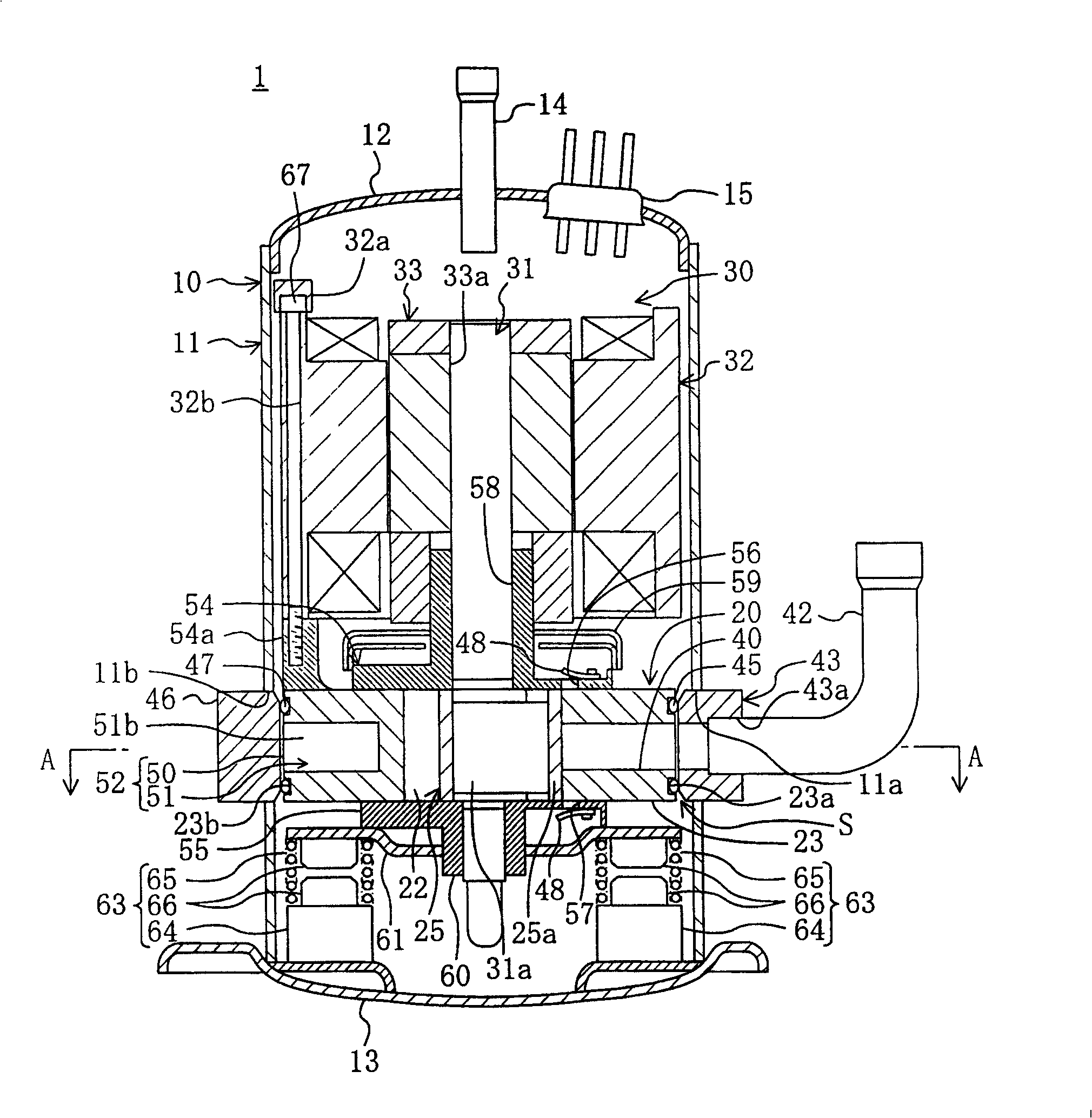
[0114] figure 1 This is the invention according to the first embodiment of the present invention. In this first embodiment, the case where the present invention is applied to a so-called rocking piston type rotary compressor 1 is shown. The compressor 1 performs a refrigerant compression process in the refrigeration cycle of the air conditioner.

[0115] In the compressor 1 described above, the compression mechanism 20 and the motor 30 are accommodated in the airtight container 10 . The drive shaft 31 of the compression mechanism 20 has its axial direction in the up-down direction. The motor 30 is provided on the upper side of the compression mechanism 20 and connected to the drive shaft 31 of the compression mechanism 20 . The motor 30 is integrated with the compression mechanism 20 elastically supported in the airtight container 10 by the support mechanism 63 .

[0116] The airtight container 10 includes: a cylindrical shell 11 that is long in the vertical direction, a bo...

no. 2 Embodiment

[0177] Figure 6 A rotary compressor according to a second embodiment of the present invention is shown. The rotary compressor of this embodiment is the same as that of the first embodiment except for the structures of the sealing mechanism S, the interface member 43 and the block member 46 . In the following description, the same parts as those in the first embodiment are given the same symbols, and only the parts different from them will be described in detail.

[0178] In this embodiment, also as Figure 7 As shown, the peripheral portion of the suction passage 40 on the outer surface of the cylinder 23 is a flat surface substantially perpendicular to the radial direction of the cylinder 23, and this flat surface serves as a sealing surface. On the other hand, the front end side portion of the interface member 43 is formed in a cylindrical shape, and this portion constitutes the cylindrical portion 71 . Then, the sealing member 72 is fitted into the cylindrical portion 7...

no. 3 Embodiment

[0204] The third embodiment of the present invention is an embodiment in which the structure of the compressor of the above-mentioned first embodiment is changed. Here, differences between this embodiment and the first embodiment described above will be described.

[0205] Such as Figure 12 and Figure 13 As shown, in the compressor 1 of the present embodiment, the block member 46, the suction pressure chamber 50, and the communication path 51 are omitted. Furthermore, in this embodiment, the shape of the interface member 43 is different from that of the first embodiment described above.

[0206] The interface member 43 of this embodiment is formed in a cylindrical shape. One end of the suction tube 42 is inserted and fixed to the base end side of the through hole 43 a provided in the mouthpiece member 43 . The interface-side insertion hole 11 a provided in the body 11 of the airtight container 10 has a higher lower end and a lower upper end than the compression mechanism...


PUM


Abstract

In a cylinder (23) of a compression mechanism (20), an intake passage (40) passing through the cylinder (23) in the radial direction thereof is formed. There is provided in a sealed container (10) a coupling member (43) having a tip end face facing the periphery of the intake passage (40) in the outer face of the cylinder (23) and a base end to which an intake pipe (42) is mounted. The tip end face of the coupling member (43) serves as a flat sealed face. A concave groove (23a) is formed in a peripheral part around the intake passage (40) in the outer face of the cylinder (23) and an O ring (45) is fitted therein. The O ring (45) is pressed against the tip end face of the coupling member (43), sealing a gap between the cylinder (23) and the coupling member (43).

Description

technical field [0001] The invention relates to a compressor in which a motor is housed in an airtight container, and the motor rotatably drives a compression mechanism and a drive shaft of the compression mechanism, and particularly relates to the technical field of a structure elastically supporting the compression mechanism and the motor in an airtight container. Background technique [0002] Hitherto, a hermetic rotary compressor in which an electric motor is mounted on the upper side of the compression mechanism to integrate the two, and a coil spring is interposed between the above-mentioned compression mechanism and the bottom wall of the airtight container is known (for example, refer to Patent Document 1: Japanese Patent Laid-Open Publication No. 1-203688). In this compressor, by elastically supporting the compression mechanism and the motor, the vibration transmitted from the compression mechanism and the motor to the airtight container is suppressed, and the noise...

Claims


Application Information

Patent Timeline
Patent Type & Authority Patents(China)
IPC IPC(8): F04C29/00F04C23/02F04C27/00
Inventor 清水孝志芝本祥孝浅野能成
Owner DAIKIN IND LTD
Why Eureka
Try Eureka