
Oil-gas spring

A technology of oil and gas springs and driving springs, applied in springs/shock absorbers, elastic suspensions, gas-liquid shock absorbers, etc., can solve the problems of increased design, gas leakage, and small piston extension strokes, and achieves manufacturing and maintenance. Convenience, impact reduction, and the effect of extending the inflation interval

Inactive Publication Date: 2008-10-22
仇恒超
View PDF6 Cites 0 Cited by
  • Summary
  • Abstract
  • Description
  • Claims
  • Application Information

AI Technical Summary

Problems solved by technology

[0005] However, the oil-pneumatic springs in the prior art only have the functions of compression and stretching. To keep the suspension at a suitable height when the vehicle is heavily loaded or unloaded, it is necessary to add another set of devices that can adjust the oil capacity and air pressure, and the air volume is small. If the piston stretching stroke is too small, the elasticity will be poor. If the air volume is too large, the piston will hit the bottom of the hydraulic cylinder and even pull out the working cylinder. Although some oil and gas springs add a secondary working cylinder , to limit the excessive stretching of the piston and avoid the piston hitting the bottom of the working cylinder. However, after the machine has been used for a long time, its performance variation makes the design more difficult and difficult to master. In addition, the gas is easy to flow from the joint of the spherical air chamber or the hydraulic cylinder head and Leakage at the junction between the cylinders requires special equipment to supplement, which brings inconvenience to use
[0006] Therefore, although existing oil-pneumatic springs have appeared for many years, they are generally only used on some mine heavy locomotives, but are seldom used on general ordinary vehicles.

Method used


Image

  • Oil-gas spring
  • Oil-gas spring
  • Oil-gas spring

Examples


Embodiment Construction

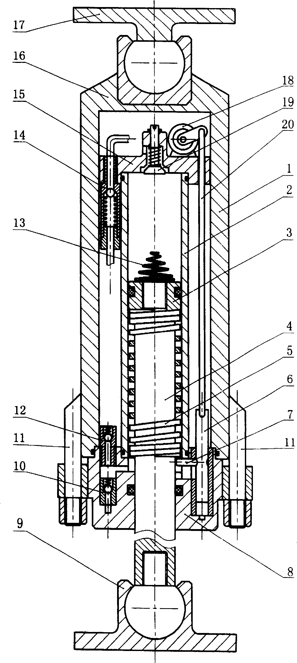
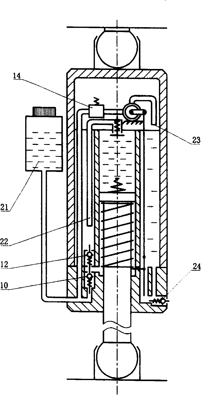
[0019] Below in conjunction with accompanying drawing, structural principle and working principle of the present invention are specifically described:

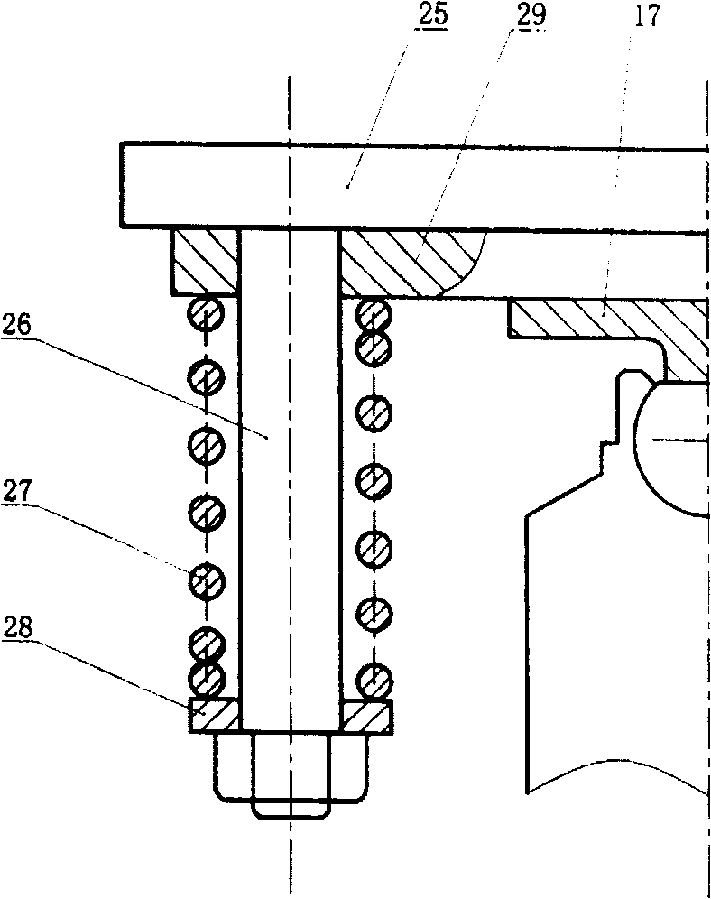
[0020] The outer cylinder barrel 1 is used as a container for storing oil and high-pressure gas, and is used as a casing at the same time, and its upper end is sealed by an outer cylinder cover 16 by welding or other means. The upper end of the outer cylinder head 16 is connected to the vehicle frame through the upper spherical hinge plate 17, the lower end of the outer cylinder 1 is socketed with the base 8 at the open end, and there is a sealing ring in between, and the outer cylinder 1 and the base 8 are pulled together by bolts 11. Tight fix. The inner cylinder 2 is used as the working cylinder for pushing the oil, and it is set inside the outer cylinder 1. The upper end is pressed by the inner cylinder head 15, and there is a sealing ring in between, and the lower end is socketed with the base 8, and there is a sealing ri...


PUM


Abstract

The invention discloses a gas oil spring, especially a gas oil spring that can control the extension length and change pressure and support force automatically as the spring element on the vehicle suspensions. The outer cylinder store the oil and high pressure air, the inner cylinder is used as working cylinder; pressing the oil out of the outer cylinder to improve the oil, air is compressed or expansion and has the function of spring. When the piston moves up and down, draw the outside oil into the outer cylinder to enhance the extension distance and attenuate part of the extension power to play the function of buffer. When the extension distance get the limit height, the decompression valve is driven to exhaust the additional oil in the outer cylinder, make the extension height and support force adapt the load status under the function of the oil cycling.

Description

technical field [0001] The invention relates to an oil-pneumatic spring capable of automatically controlling the stretching height and changing the working pressure and supporting force by itself, belonging to the technical field of hydraulic machinery and motor vehicle applications, and mainly used as an elastic element for vehicle suspension as a bearing. Background technique [0002] In the prior art, the oil-gas spring uses gas (usually nitrogen) as the elastic medium and oil as the force transmission medium, and is mainly composed of hydraulic cylinder, piston, thrust cylinder and damping valve seat, etc., and is divided into two parts: There are two types of oil and gas separation type and oil and gas non-separation type. The oil and gas separation type usually has an extra spherical air chamber, and the oil and gas are separated by a rubber diaphragm. The oil and gas non-separated type is due to the relationship between the specific gravity of oil and gas and the non-...

Claims


Application Information

Patent Timeline
Patent Type & Authority Patents(China)
IPC IPC(8): F16F9/06F16F15/027B60G13/06B60G13/00
Inventor 仇恒超
Owner 仇恒超
Learn More