
Gate-cathode structure design method for gate pole converting thyristor GCT

A technology of gate commutation and cathode structure, which is applied in thyristors, calculations, and special data processing applications, etc., can solve the problems of current capacity limitation and small effective cathode area, and achieve the improvement of on-state current capacity and increase of effective cathode area. Effect

Inactive Publication Date: 2008-10-22
XIAN UNIV OF TECH
View PDF1 Cites 0 Cited by
  • Summary
  • Abstract
  • Description
  • Claims
  • Application Information

AI Technical Summary

Problems solved by technology

[0004] In order to solve the problem that the current capacity is limited due to the small effective cathode area in the existing GCT gate-cathode structure, the object of the present invention is to provide a gate-cathode structure design method for gate-commutated thyristor GCT. The gate-cathode structure obtained by the method can increase the effective cathode area and improve the current capacity of the device without affecting the current uniformity in the switching process of the GCT device

Method used


Image

  • Gate-cathode structure design method for gate pole converting thyristor GCT
  • Gate-cathode structure design method for gate pole converting thyristor GCT
  • Gate-cathode structure design method for gate pole converting thyristor GCT

Examples


Embodiment Construction

[0059] The present invention will be described in detail below in conjunction with the accompanying drawings and specific embodiments.

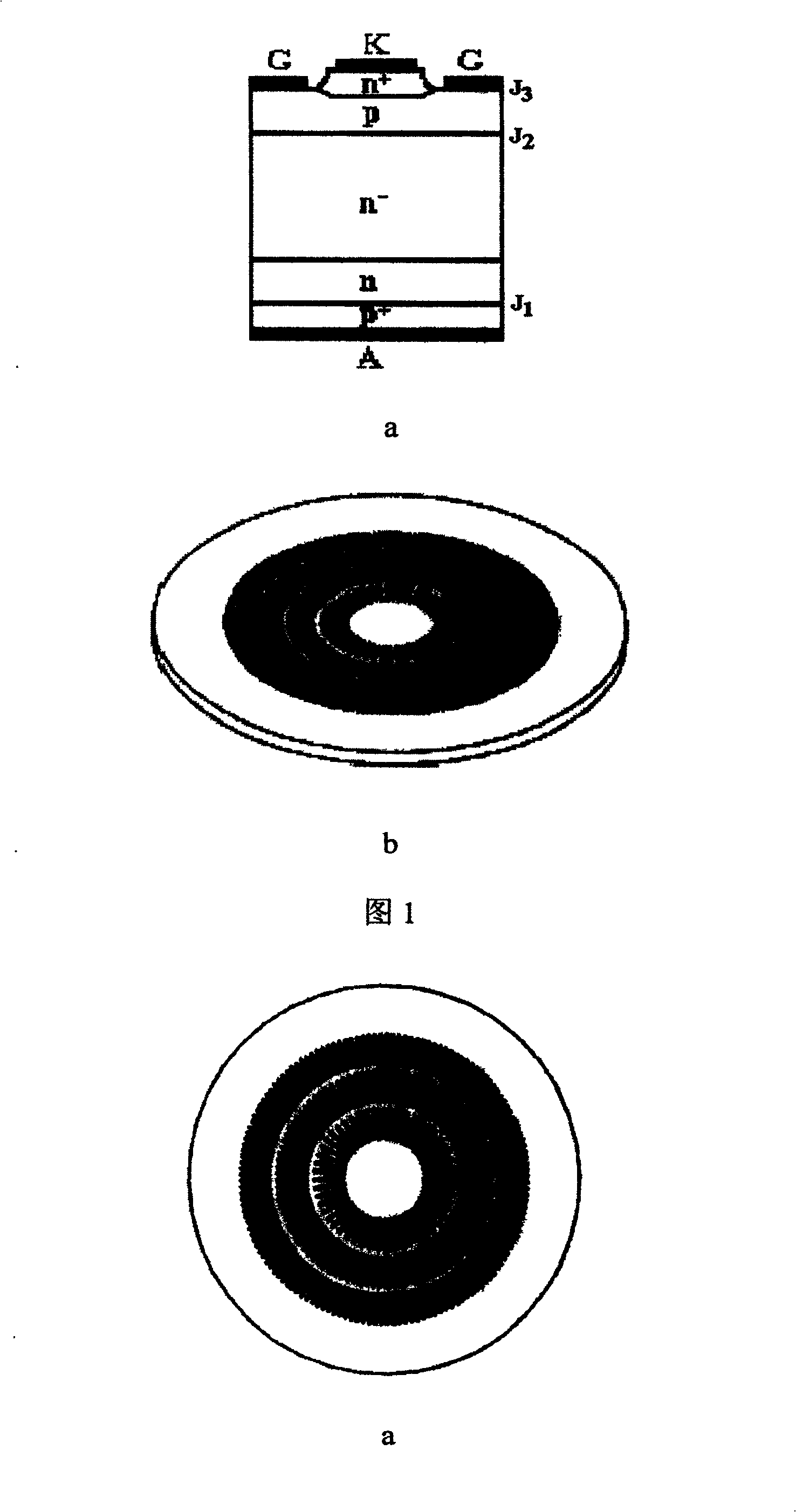
[0060] Figure 1a is a schematic cross-sectional view of the basic structure of the existing GCT, which is an additional transparent anode p in the GTO tube core structure + area and buffer layer n area, by n + pn - np + Composition, and realize the turn-on and turn-off of the device through the hard drive. Its gate-cathode structure follows the gate-cathode structure of GTO, as shown in Figure 1b. In addition, in Figure 1a, G represents the gate, K represents the cathode, A represents the anode, and J 1 Indicates the anode emitter junction P + n junction, J 2 Indicates a Pn-junction, J 3 Indicates the cathode emitter junction Pn + Knot.

[0061] figure 2 The gate-cathode pattern of GTO is shown, where b is an enlarged view of the GTO die with aluminum electrodes. Its cathode emitter structure is rectangular finger strips arranged in...


PUM


Abstract

This invention discloses a gate-cathode structure design method for GCT including: determining the gate-cathode lateral diameter, a ladder cathode unit graphic diameter and its surrounding diameter of the GCT, then determining the number of the ladder cathode units and finally determining the unit number arrayed on each ring and designing the cathode in a ladder shape arrayed on the total cathode face with the area getting smaller from inside to outside.

Description

technical field [0001] The invention belongs to the technical field of power semiconductor devices, and relates to a gate-cathode structure design method of a thyristor, in particular to a gate-cathode structure design method of a gate-commutated thyristor GCT. Background technique [0002] Gate commutated thyristor GCT is a new type of power semiconductor device, which is developed on the basis of gate turn-off thyristor GTO. Gate-commutated thyristor GCT adds two technologies to the existing GTO core structure, namely, the transparent anode p+ region and the buffer layer n region, which are composed of n+pn-np+, and the device is turned on and off through hard drive broken. Its gate-cathode structure follows the gate-cathode pattern of GTO, and adopts the cathode-emitter structure with rectangular fingers arranged in concentric rings, which is generally popular in the world. Mesa thyristors surrounded by "sea". [0003] GTO uses this discrete cathode unit mainly to solv...

Claims


Application Information

Patent Timeline
Patent Type & Authority Patents(China)
IPC IPC(8): H01L21/332H01L29/74G06F17/50
Inventor 王彩琳高勇
Owner XIAN UNIV OF TECH
Learn More