
Dry method coating device

A kind of coating and equipment technology, applied in the field of dry coating equipment based on electrostatic fluidized bed, can solve the problems of small coating thickness, particle rebound, affecting coating efficiency, etc., and achieve the effect of safe use and uniform dispersion

Inactive Publication Date: 2012-11-28
罗彦凤
View PDF1 Cites 0 Cited by
  • Summary
  • Abstract
  • Description
  • Claims
  • Application Information

AI Technical Summary

Problems solved by technology

[0005] ① Corona discharge spray gun: It is easy to produce reverse ionization, especially for weakly conductive solid dosage forms, resulting in a small coating thickness, which requires multiple sprays to increase the thickness and affects the coating efficiency; the spray gun needs to use 20 ~ 120KV High-voltage electrodes, sometimes the operator needs to directly operate or observe closely, and the safety is not ideal
[0006] ②Frictional electrostatic spray gun: In order to achieve higher frictional electricity generation efficiency, the flow rate of the airflow carrying the dry powder is usually higher than that of the corona discharge spray gun; when the high-speed airflow and powder enter the coating pan, due to the limited space of the coating pan, the spray gun It is close to the solid preparation, so it is easy to produce serious particle rebound, offset part of the electrostatic attraction, and disturb the movement direction of the powder airflow, thereby damaging the uniformity of powder distribution and coating thickness

Method used


Image

  • Dry method coating device
  • Dry method coating device
  • Dry method coating device

Examples


Embodiment Construction

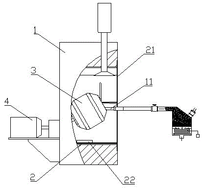
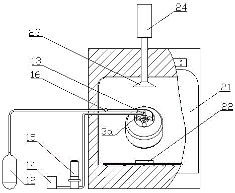
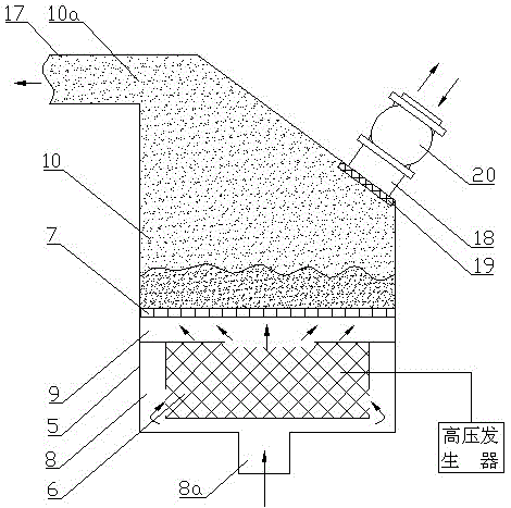
[0022] figure 1 It is a structural schematic diagram of the present invention, figure 2 for figure 1 The right side view of the electrostatic fluidized bed is removed from the image 3 It is a structural schematic diagram of an electrostatic fluidized bed, as shown in the figure: the dry coating equipment of this embodiment includes a box body 1, a coating device, an electrostatic fluidized bed and an auxiliary material supply device; the box body 1 is provided with Heat source 2; the coating device includes a cylindrical coating pan 3 with an open end and a coating pan driving assembly 4 for driving the coating pan 3 to rotate around its own axis. In this embodiment, the coating pan driving assembly is The motor and the speed changer are easy to realize, and both are arranged outside the casing, which can avoid dust pollution and damage the motor and the speed changer. The coating pan 3 is arranged in the casing 1, and a rotating shaft is arranged at the bottom thereof, an...


PUM


Abstract

The invention provides a dry method coating device, comprising a case, a coating device, an electrostatic fluidized bed and an accessories supplying device. When the dry method coating device is used, the airflow is ionized after passing through a high voltage electrode and is acted on the powder which is arranged within a fluidization room of the fluidized bed to form charged powder flue gas, then the charged powder flue gas is conveyed to a rotary coating pan; simultaneously, the accessories such as plasticizer and the like are quantitatively transmitted to an atomizer to form a fog which is evenly distributed, the fog is simultaneously or stepwise entered into the pan together with dry powders, the dry powders are evenly attached on the outer surface of a solid preparation and then thedry powders are quickly softened by regulating the ambient temperature to an appropriate degree so as to form a coating layer and to realize the purpose of efficient coating. The dry method coating device provided by the invention has the advantages that the application is safe due to the high voltage electrode is arranged within the fluidized bed, the distribution of powder flue gas is even in the case that the distance from the coating pan to the electrode is long and the distribution of powder flue gas cannot be influenced by the electric field by comparing with conventional corona electrostatic spray gun, the limitation that the airflow velocity cannot too low is prevented by comparing with friction electrostatic spray gun and the evenness of powder distribution and coating thickness can be protected.

Description

technical field [0001] The invention relates to equipment for coating solid preparations with dry powder, in particular to a dry coating equipment based on an electrostatic fluidized bed. Background technique [0002] Drug products mainly exist in two dosage forms, solid preparation and liquid preparation. In the actual production of solid preparation, due to the purpose of masking the smell of the drug, preventing moisture, avoiding light, controlling the release site and release rate of the drug during use, it is necessary to use a specific The material is coated with it. [0003] At present, the equipment used to coat pharmaceutical solid preparations in the pharmaceutical industry is mainly a wet coating machine. After mixing the coating material with a solvent, it is attached to the surface of the solid preparation by spraying or printing through a wet coating machine. Then dry the obtained solid preparation to form a uniform and smooth protective layer on the surface ...

Claims


Application Information

Patent Timeline
Patent Type & Authority Patents(China)
IPC IPC(8): A61J3/06
Inventor 罗彦凤
Owner 罗彦凤
Learn More