Method and plant for manufacturing cement clinker

A cement clinker and equipment technology, applied in the field of cement manufacturing, can solve the problems that raw materials cannot be calcined optimally, and are not mixed with fuel to the required degree to provide

Inactive Publication Date: 2008-11-12
F L SMIDTH & CO AS
View PDF5 Cites 2 Cited by
  • Summary
  • Abstract
  • Description
  • Claims
  • Application Information

AI Technical Summary

Problems solved by technology

However, an obvious disadvantage of this type of furnace installation is that the raw meal discharged from the calciner is not optimally calcined
Also, the exhaust gases exiting the calciner may contain unburned fuel, a significant portion of which is in the form of carbon monoxide, because the combustion gases have not been mixed with the fuel to the extent required to provide the necessary cut-off across the entire calciner. area of ​​remaining air

Method used


Image

  • Method and plant for manufacturing cement clinker
  • Method and plant for manufacturing cement clinker
  • Method and plant for manufacturing cement clinker

Examples


Embodiment Construction

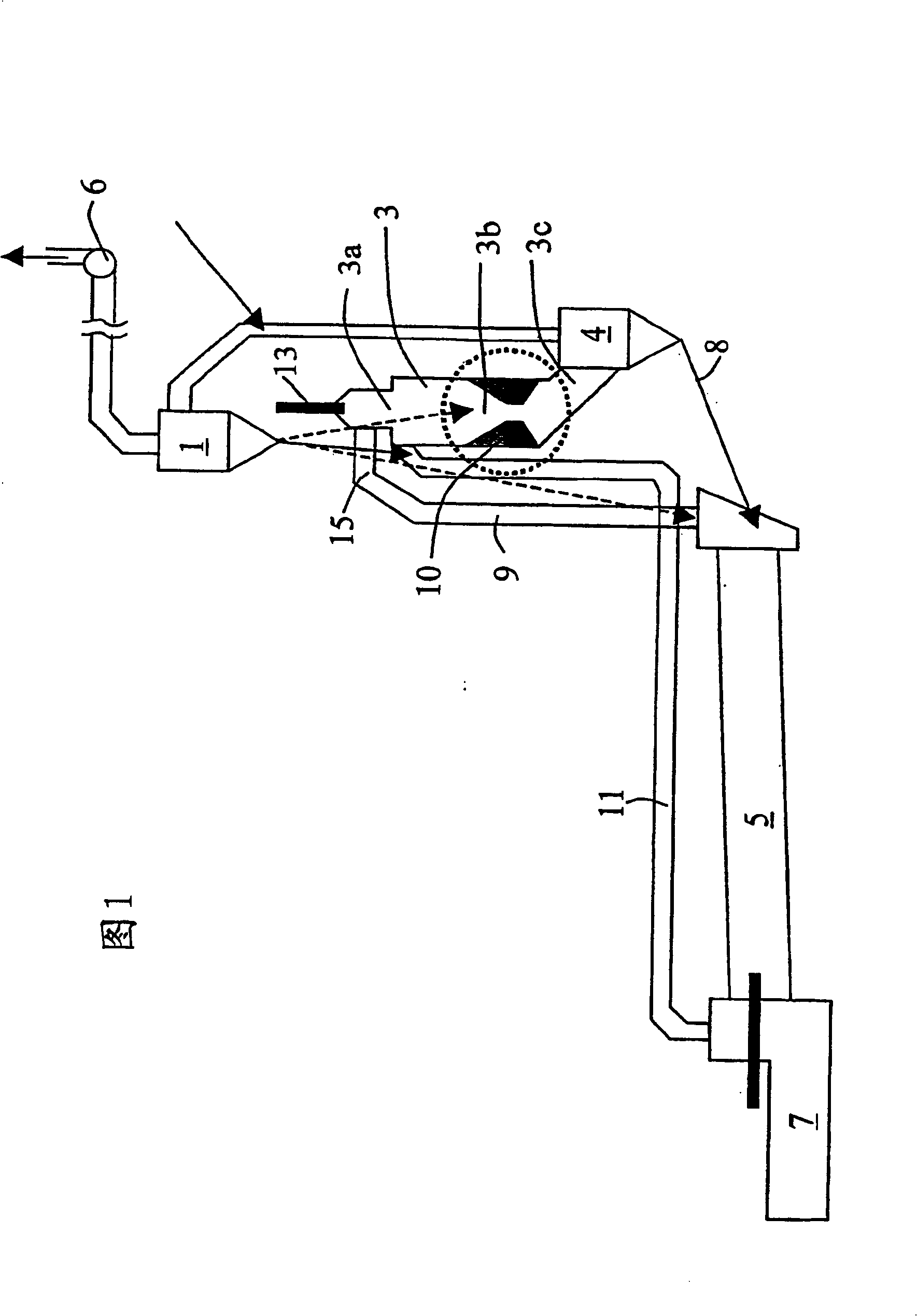
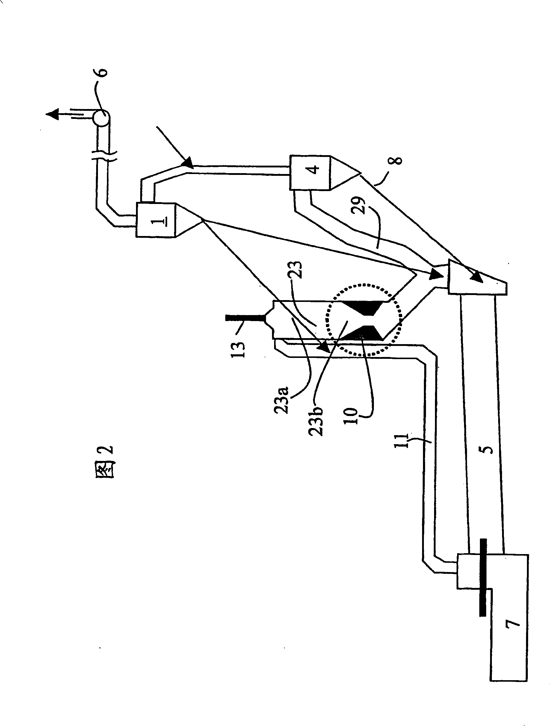
[0015] In Fig. 1, a furnace plant of type ILC-D for manufacturing cement clinker is shown. The plant comprises: a cyclone preheater, of which only the last cyclone 1 is shown; a calciner 3 with a separation cyclone 4; a rotary kiln 5; and a clinker cooler 7. The plant also comprises a furnace gas riser 9 for feeding furnace exhaust gases to the calciner 3 and a duct 11 for leading preheated air from the clinker cooler 7 to the calciner 3 . The preheated raw meal is separated from the preheater in the cyclone 1 and directed to the calciner 3 for calcination. Thereafter, from the bottom outlet of the separation cyclone 4, the calcined raw meal is guided via a pipe 8 into a rotary kiln 5, where it is burned into cement clinker and subsequently Cool in clinker cooler 7. Exhaust gases from the rotary kiln 5 and the calciner 3 are sucked from the calciner 3 through the cyclone 4 and upstream through the preheater by means of a schematically shown fan 6 .

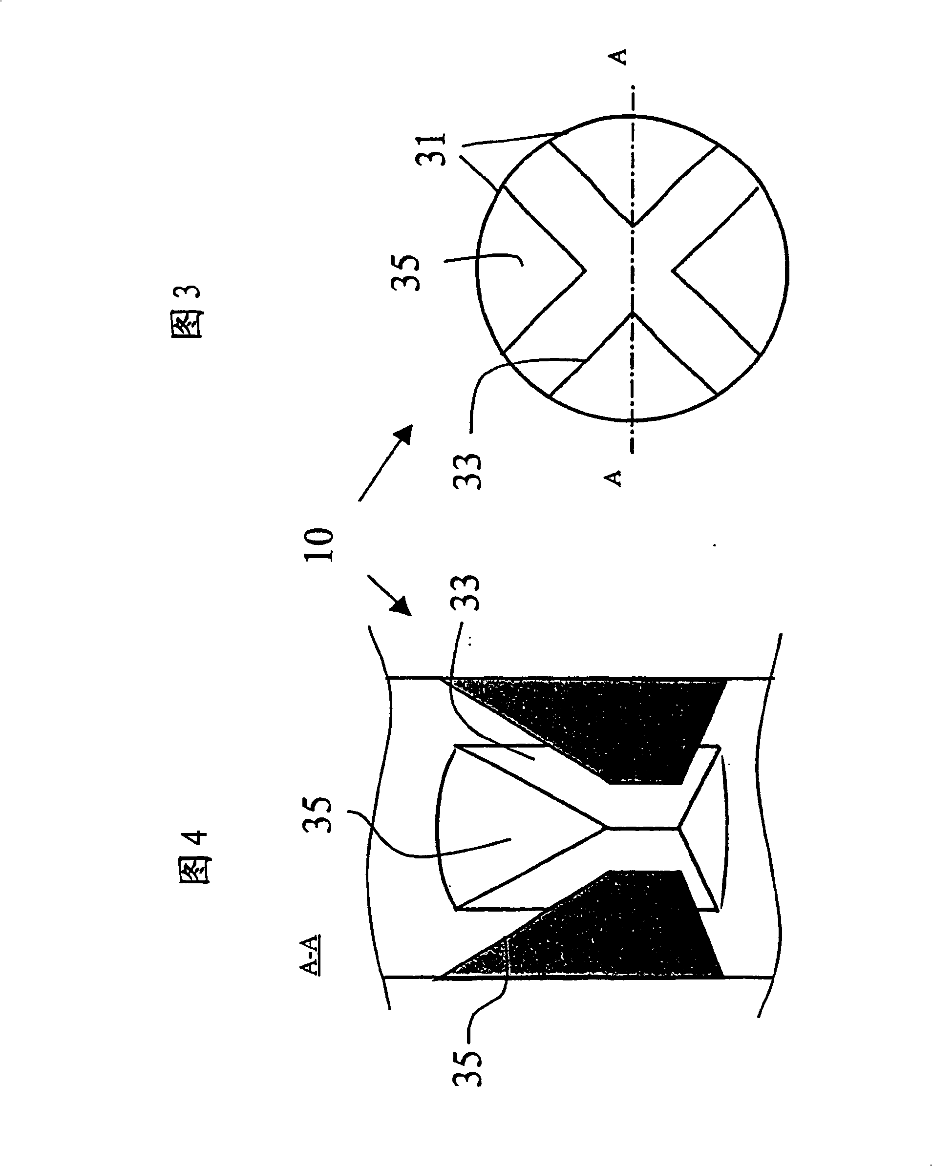
[0016] In the embodimen...


PUM


Abstract

A method and plant for manufacturing cement clinker are disclosed, in which cement raw meal is calcined in a calciner (3, 23). The calciner (3, 23) comprises an upper zone (3a, 23a) and a lower zone (3b, 23b), where fuel, combustion gas and raw meal are introduced into the upper zone of the calciner and directed downward through the calciner. The combustion gas and raw meal are introduced tangentially into the calciner and subject to rotation follow a spiral-shaped flow path, and, under the action of gravity, the raw meal is primarily directed down along the wall of the calciner. The rotation of the combustion gas in at least the lower zone of the calciner is subjected to braking and approximately simultaneously or subsequently at least some of the combustion gas and at least some of the raw meal in the lower zone of the calciner is directed in the direction towards the centre-line of the calciner.

Description

technical field [0001] The present invention relates to methods and apparatus for the manufacture of cement, and more particularly to methods and apparatus for the manufacture of cement clinker. Background technique [0002] Plants of the above-mentioned type for the manufacture of cement are known in the prior literature. [0003] An example of a Separate Line Calculator Downdraft (SLC-D) furnace installation is known from US Patent No. 4014641 and WO97 / 30003. Plants of this type comprise a calciner constructed as a chamber, which is connected at its lower end to an upper guiding gas duct which is simultaneously connected to the outlet end of the furnace for exhaust gases. In addition, an in-line calcinator downdraft (ILC-D) furnace installation is known from International Patent Application No. PCT / IB01 / 01296, wherein the calcinator exists in a large chamber in the subject. A common feature of both types of equipment is that most of the fuel used in the calciner is inje...

Claims


Application Information

Patent Timeline
Patent Type & Authority Patents(China)
IPC IPC(8): F27B7/20C04B7/43C04B7/44F27B1/00F27B1/21F27D5/00
CPCF27B7/2033C04B7/434C04B7/43F27B7/20
Inventor 拉尔斯·S·延森
Owner F L SMIDTH & CO AS
Why Eureka
Try Eureka