Rise and fall assembly rack for engine
An assembly frame and engine technology, applied in assembly machines, metal processing equipment, manufacturing tools, etc., can solve the problems of affecting assembly speed and assembly quality, on-site management confusion, easy to fall, etc., and achieve the improvement of assembly work environment. Assembly quality, the effect of eliminating potential safety hazards
- Summary
- Abstract
- Description
- Claims
- Application Information
AI Technical Summary
Problems solved by technology
Method used
Image
Examples
Embodiment 1
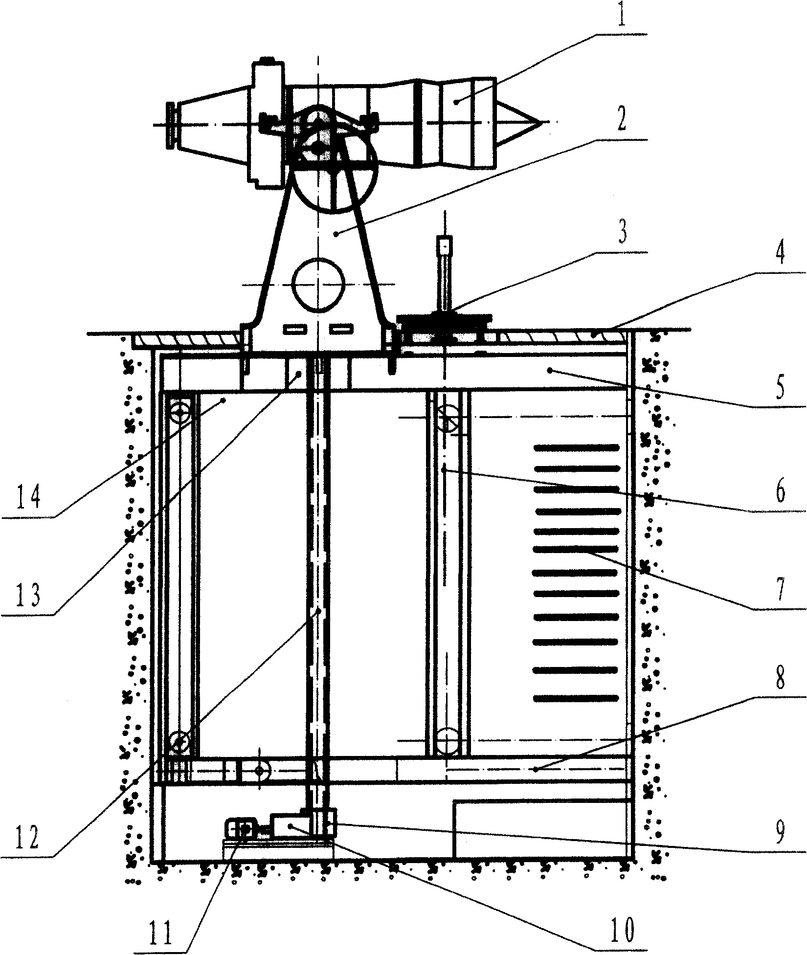
[0017] As a preferred embodiment of the present invention, such as figure 1 . A pit 14 is arranged under the ground of the factory building, and a lifting device 23 is installed in the pit 14, and a lifting platform 5 is fixedly connected to the lifting device 23 . Said lifting platform 5 is provided with an assembly frame 2 for assembling the engine and an auxiliary assembly frame 3, and the assembly frame 2 can rotate 360° along its supporting axis. The engine assembly is first assembled on the auxiliary assembly frame 3, and then moved to the assembly frame 2 to be assembled with other components. The lifting device 23 can be a variety of hydraulic or mechanical transmissions, such as figure 1 , figure 2 , image 3 shown. figure 1 The lifting device 23 is composed of a worm gear mechanism 9, a gear box 10 and a motor 11. The lifting platform 5 is set on the two screw rods 12 with a nut 13. The lifting platform 5 is also provided with rollers and guide rails 6. The low...
Embodiment 2
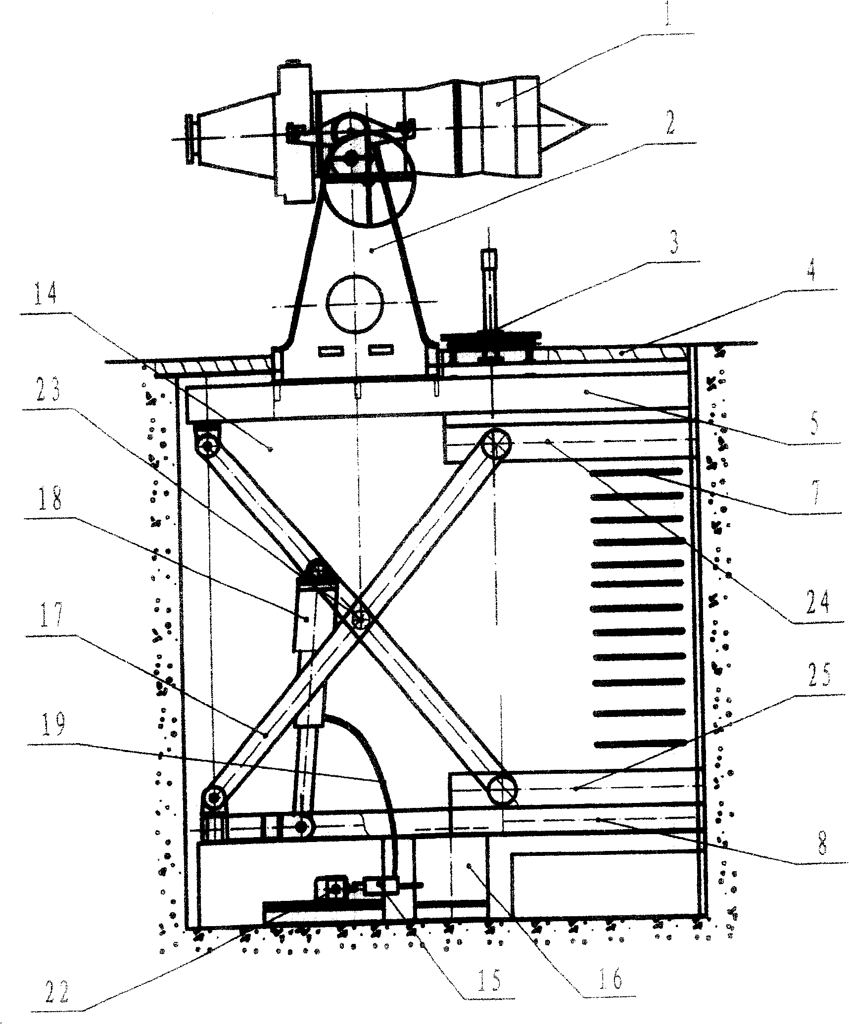
[0019] Another preferred embodiment of the present invention is figure 2 , and the other structures remain unchanged. Described lifting device 23 is made up of high-pressure oil pump 15, oil tank 16, two sets of support rods 17, and hydraulic cylinder 18. A hydraulic guide rail 24 is fixedly connected to the lifting platform 5, and a horizontal guide rail 25 is also fixed on the pit 14 and the base 8. One end of two sets of four support rods 17 is respectively fixed on the hydraulic guide rail 24 and the lateral guide rail 25, and the other ends are fixed respectively. On the base 8 and the lifting platform 5, the hydraulic guide rail 24 moves up and down with the lifting platform 5. The driving motor 22 drives the high-pressure oil pump 15, and the high-pressure oil is delivered to the actuator cylinder 18, which pushes the actuator cylinder to generate axial displacement, and drives the support rod 17 to move bidirectionally so that the lifting platform 5 moves up and down...
Embodiment 3
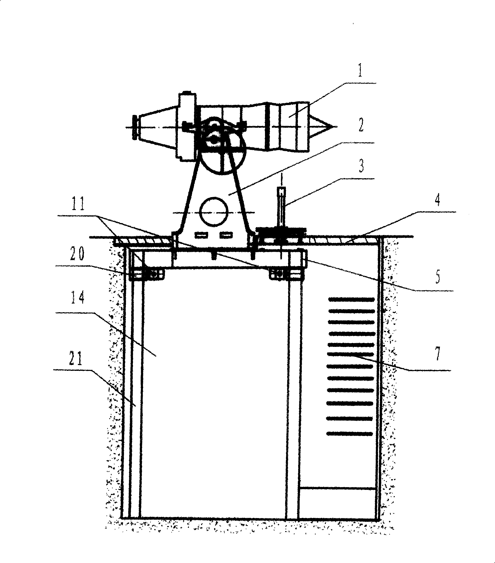
[0021] Mounting frame of the present invention also can adopt such elevating mechanism, see image 3 . Described lifting device 23 is made up of gear 20 , rack 21 and driving motor 22 . There are four racks 21 inherent on the wall of the pit, and four gears 20 inherent on the lifting platform 5 . Drive motor 22 drives four gears 20 on the lifting platform 5 to roll on the four racks 21 installed vertically to achieve the purpose of lifting.
[0022] When the assembly work starts, the worker opens the pit cover 4, automatically lifts the assembly frame 2 from the pit 14 to the ground through the operating mechanism, fixes it when it reaches the required height, and starts the assembly work. The lifting platform 5 and the assembly frame 2 can be automatically lowered to below the ground, and the cover plate 4 is covered to form a level ground.
PUM
 Abstract
Description
Claims
Application Information
 - Generate Ideas
- Intellectual Property
- Life Sciences
- Materials
- Tech Scout
- Unparalleled Data Quality
- Higher Quality Content
- 60% Fewer Hallucinations
Browse by: Latest US Patents, China's latest patents, Technical Efficacy Thesaurus, Application Domain, Technology Topic, Popular Technical Reports.
© 2025 PatSnap. All rights reserved.Legal|Privacy policy|Modern Slavery Act Transparency Statement|Sitemap|About US| Contact US: help@patsnap.com


