Caution device of monitoring low voltage distribution line

A warning device, low-voltage power distribution technology, applied in the direction of alarms, instruments, etc., can solve the problems of poor reliability, easy to be damaged, troublesome installation and use management, etc., and achieve the effect of high reliability and strong anti-destructive ability.

Inactive Publication Date: 2008-12-31
时均泉
View PDF11 Cites 0 Cited by
  • Summary
  • Abstract
  • Description
  • Claims
  • Application Information

AI Technical Summary

Problems solved by technology

[0004] Although this utility model has the function of anti-theft alarm, it is easy to be destroyed, has poor reliability, the anti-theft effect is not ideal, and installation and use management are relatively troublesome.

Method used


Image

  • Caution device of monitoring low voltage distribution line

Examples


Embodiment Construction

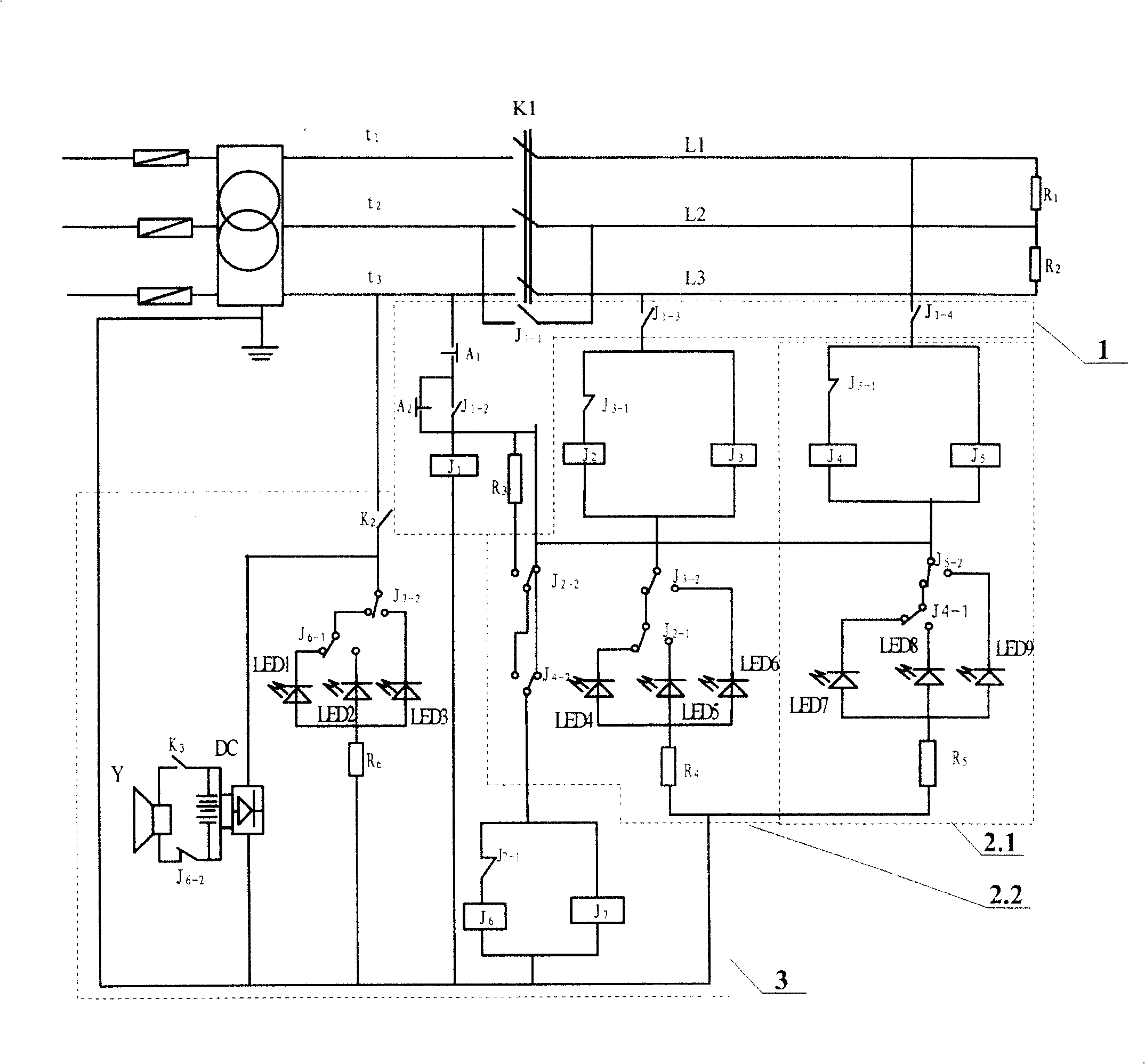
[0011] The present invention will be further described below in conjunction with accompanying drawing and specific embodiment:

[0012] A low-voltage distribution line monitoring and warning device, such as figure 1 As shown, it includes power output lines t1, t2, t3 and three-phase electrosurgical switch K1 and speaker Y. There are monitored power lines L1, L2, L3 corresponding to the power output lines t1, t2, t3 respectively, the ends of the power lines L1, L2 are connected with the terminal current limiting resistor R1, and the ends of the power lines L2, L3 are connected with the terminal Current limiting resistor R2; power output line t2 and power line L2 are controlled by switch J1-1; power line L1 is connected to the first wire monitor 2.1 through the central controller, and power line L3 is connected to the second wire monitor through the central controller 1 The wire monitor 2.2; the first and second wire monitors 2.1, 2.2 act together on the alarm display 3; the ce...


PUM


Abstract

A monitor-alarming device of low voltage distribution line is prepared for setting power supply output line at front end of three-phase knife blade switch, connecting monitored power line at back end of three-phase knife blade switch, connecting tail end throttle resistances at tail end of power line, using switch to control power supply line and power line and connecting power lines with monitors through central controllers.

Description

technical field [0001] The invention relates to a combined alarm device for monitoring low-voltage power distribution lines, which belongs to the technical field of electronic alarms. Background technique [0002] The inventor applied on June 10, 2004, and was authorized on February 1, 2006. The patent No. is ZL200420041249.9, and the utility model name is "wire anti-theft cutting alarm device", which discloses a wire anti-theft cutting alarm device. The utility model belongs to the technical field of electronic alarm. It has a knife switch, a three-phase electric circuit, a speaker, a resistor and a relay are provided at the terminal of the circuit, and a relay and a speaker are provided behind the circuit knife switch. [0003] Its sovereign item is "1. a kind of electric wire anti-theft cutting alarm device has knife switch K1, three-phase electric circuit, line (1), line (2), line (3), loudspeaker (8), it is characterized in that: At the terminal of the line, resistors...

Claims


Application Information

Patent Timeline
Patent Type & Authority Patents(China)
IPC IPC(8): G08B21/00
Inventor 时均泉
Owner 时均泉
Why Eureka
Try Eureka