Tension mechanism adapted for automatic optical fiber winding machine
What is AI technical title?
AI technical title is built by PatSnap AI team. It summarizes the technical point description of the patent document.
An optical fiber winding machine and tension mechanism technology, applied in the directions of light guides, optics, optical components, etc., can solve the problems of inability to guarantee the winding quality, unstable transmission control, low tension control accuracy, etc., and achieve no reverse dead zone, Improved tension control accuracy and low friction effects
Inactive Publication Date: 2009-01-21
BEIHANG UNIV
View PDF5 Cites 1 Cited by
Summary
Abstract
Description
Claims
Application Information
AI Technical Summary
This helps you quickly interpret patents by identifying the three key elements:
Problems solved by technology
Method used
Benefits of technology
Problems solved by technology
How to wind a high-quality fiber optic ring is very important to the development of fiber optic gyroscopes. There are many winding methods, and the quadrupole symmetrical winding method has the best effect, which is a method commonly used in the world. Manual winding is adopted, and there is no special equipment, so the winding quality cannot be guaranteed
[0004] At present, the tension mechanism used in some automatic optical fiber winding machines has defects such as simple structure, no backlash elimination mechanism, unstable transmission control, low tension control precision, and zero point drift.
Method used
Image
Click on the blue label to locate the original text in one second.
Reading with bidirectional positioning of images and text.
Examples
Embodiment Construction
[0029] The present invention will be further described in detail below in conjunction with the accompanying drawings.
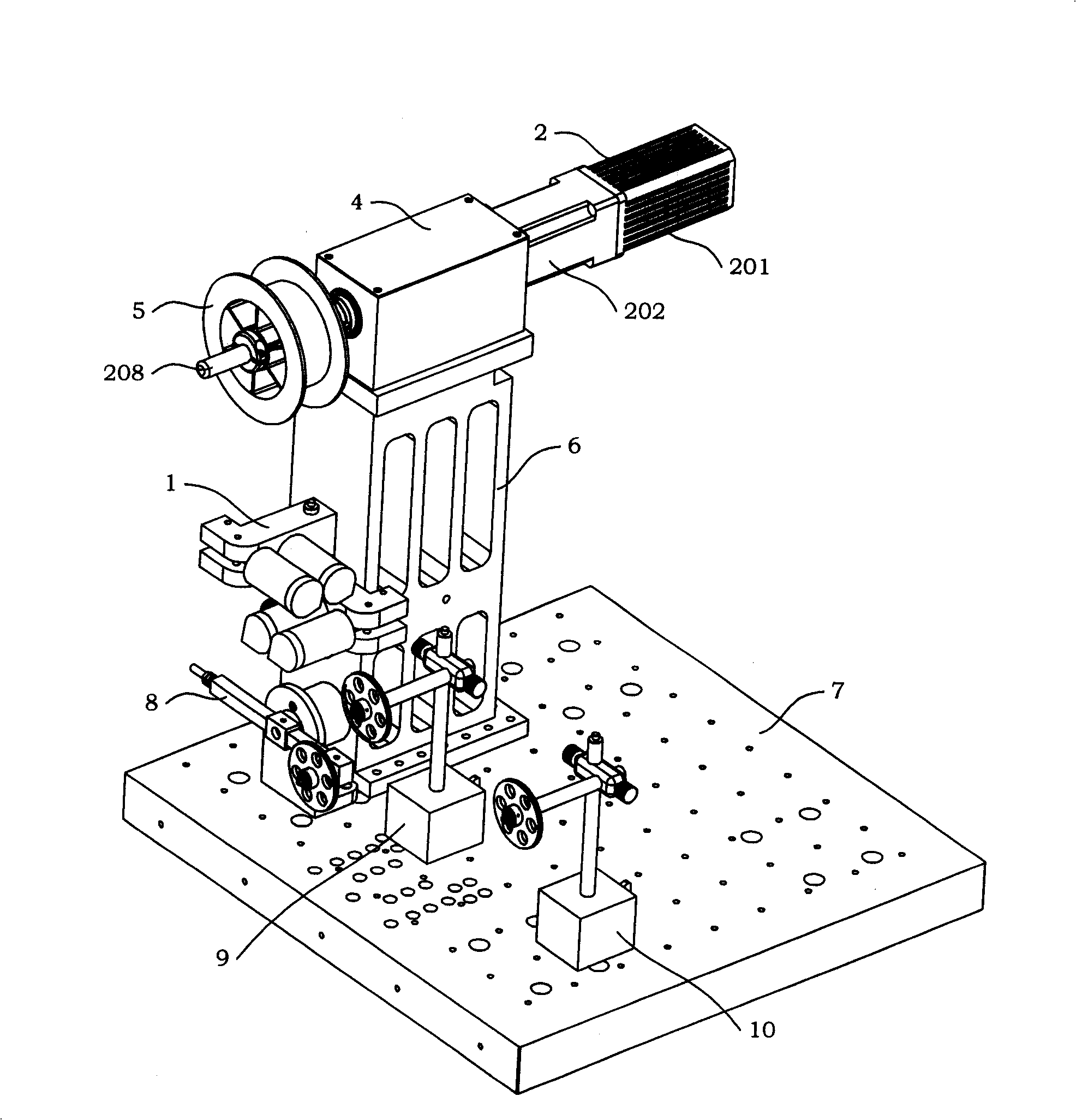
[0030] see figure 1 As shown, the present invention is a tension mechanism suitable for automatic optical fiber looping machines. Component 8, the first fiber guide component 9 and the second fiber guide component 10, the lower end of the support base 6 is installed on the slide table 7 through screws and nuts; the upper end of the support base 6 is equipped with a transmission box 4; the drive assembly 2 is installed on On the transmission box body 4, and the motor 201 and the reducer 202 are placed on the outer rear side of the transmission box body 4, the precision main shaft 208 of the drive assembly 2 is suspended on the outer front side of the transmission box body 4; the precision main shaft 208 of the drive assembly 2 is installed There is a fiber payout wheel 5; the fiber assembly assembly 1 is installed on one side of the support base 6, and mainta...
PUM
Abstract
The invention discloses a tension structure used in automatic fiber coiler, composed of a fiber collector, a driver, a transmit box, a fiber discharge wheel, a support base, and a sliding table tension element, a first fiber guider and a second fiber guider, wherein the lower end of the support base via nut and screw is mounted on the sliding table, while the upper end is mounted with the transmit box, the driver is on the transmit box, while a motor and a speed reducer are mounted at the outer back of the transmit box, the accurate shaft of the driver is suspended at the outer front of the transmit box, which is mounted with the fiber discharge wheel, the fiber collector is at one side of the support base, vertically with the fiber discharge wheel, the sliding table is arranged with a plurality of mounting holes for fixing and mounting devices, the tension element, the first and the second fiber guiders via nut and screw are fixed on the sliding table, which guide grooves are in one plane. The inventive tension device has reasonable, compact and simple structure, without reverse dead area, but with stable transmission control, accurate tension control, non-zero-bias in force measurement, digit and closed tension control.
Description
technical field [0001] The invention relates to a tension mechanism suitable for an automatic optical fiber looping machine. Background technique [0002] The fiber optic gyroscope was born in 1976. It is a new type of sensor that uses fiber optic sensing technology to measure the space inertial rotation rate. It has developed into a new mainstream instrument with epoch-making characteristics in the field of inertial technology. Compared with the laser gyroscope, it has higher precision, low cost, small size and light weight. The application prospect of fiber optic gyroscope is very broad. It is not only used for aircraft and ship navigation, missile guidance, and high-precision position control of spacecraft, but also can be used for civilian use in the guidance of high-end cars, as well as robots and automatic control systems, etc. . [0003] The fiber optic ring is the sensing core of the fiber optic gyroscope, and its basic requirements are a large extinction ratio and...
Claims
Application Information
Patent Timeline
Application Date:The date an application was filed.
Publication Date:The date a patent or application was officially published.
First Publication Date:The earliest publication date of a patent with the same application number.
Issue Date:Publication date of the patent grant document.
PCT Entry Date:The Entry date of PCT National Phase.
Estimated Expiry Date:The statutory expiry date of a patent right according to the Patent Law, and it is the longest term of protection that the patent right can achieve without the termination of the patent right due to other reasons(Term extension factor has been taken into account ).
Invalid Date:Actual expiry date is based on effective date or publication date of legal transaction data of invalid patent.

