A time-sharing processing method for signaling point reporting flow

A technology of time-sharing processing and signaling points, which is applied in the field of communication and can solve frequent problems

Inactive Publication Date: 2009-01-28
HUAWEI TECH CO LTD
View PDF3 Cites 0 Cited by
  • Summary
  • Abstract
  • Description
  • Claims
  • Application Information

AI Technical Summary

Problems solved by technology

This situation occurs more frequently when multiple signaling points are configured in the local office.

Method used


Image

  • A time-sharing processing method for signaling point reporting flow
  • A time-sharing processing method for signaling point reporting flow

Examples


Embodiment Construction

[0029] The specific implementation manners of the present invention will be described below in conjunction with the accompanying drawings.

[0030] In this technical solution, when the state change of the signaling point is reported at the MTP3 layer, the circuit resource refreshing process of each PCM system is delayed, the system load is dispersed, and the host CPU is prevented from being overloaded.

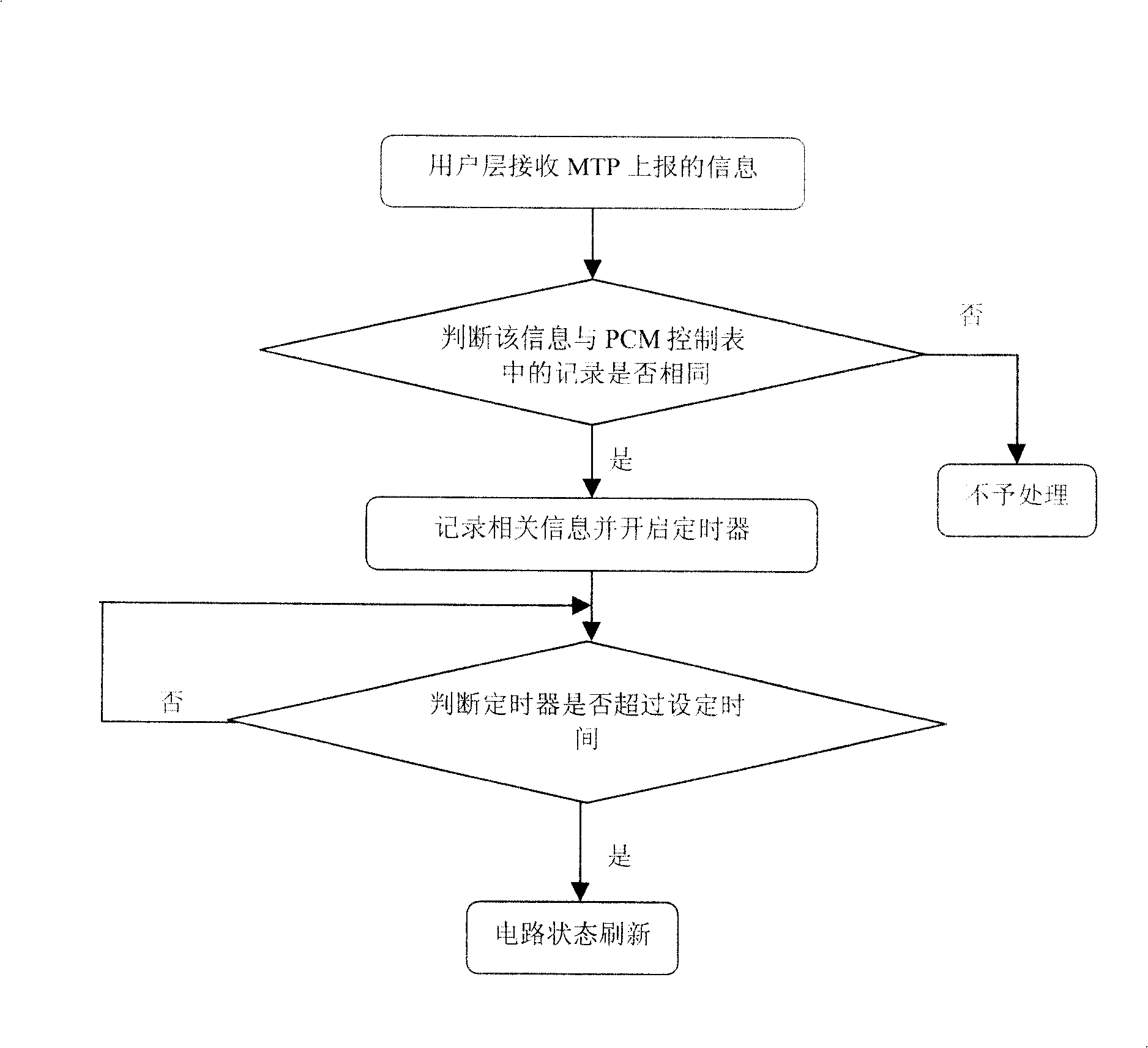
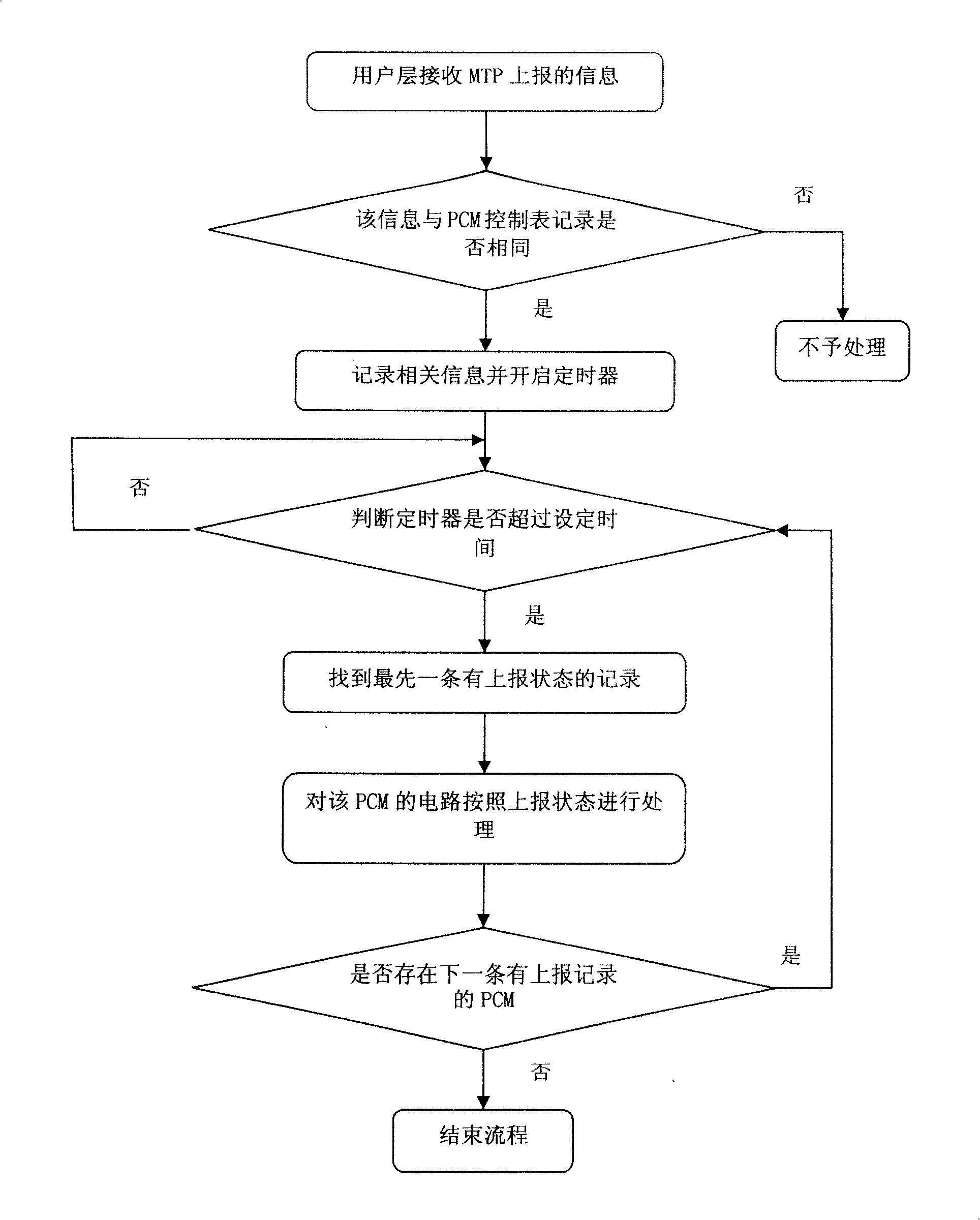
[0031] Such as figure 2 Shown is the flowchart of the time-sharing processing method of signaling point reporting process of the present invention, as can be seen from the figure, the present invention can comprise the following steps:

[0032] a. The user layer receives the information reported by the MTP;

[0033] In the prior art, the information exchange between MTP and TUP / ISUP uses MTP primitives to process the signaling message interaction between the local office and the peer end office, and at the same time report the link between the signaling point of the local of...


PUM


Abstract

This invention relates to a signaling point report flow time-sharing process method includes: a.A user layer receives MTP reported information b. to be compared with records in PCM control list c. registering coherent information and starting a timer d. judging if the timer surpasses the designed time e. finding out the first register with reported state f. processing the said PCM circuit according to the state g. judging if there is a PCM with report record in the next to return back to step d, or finish the flow if not, the invented method amends the in-all process into a time sharing process to reduce the system burden.

Description

technical field [0001] The invention relates to the field of communication, in particular to a method for filtering security features of a digital mobile exchange. technical background [0002] In mobile communication, GMSC is translated as a wireless mobile device switching center, which provides users with wireless mobile user switching, billing, authentication and other functions. The inter-office exchange usually adopts TUP (Telephone User Part) and (ISDN User Part) ISUP signaling in the No. 7 signaling system. The MTP3 (Message TransferPart) layer is similar to the third layer of the OSI model. The bottom layer is the MTP2 layer—the data link layer, and the upper layer is the user layer—TUP, ISUP, etc. Since SS7 is a standard protocol, when the state of the destination signaling point changes, the MTP3 layer will report to the user layer. The existing processing flow starts a timer of 6 seconds (for TUP signaling) or 15 seconds (for ISUP signaling) after the user laye...

Claims


Application Information

Patent Timeline
Patent Type & Authority Patents(China)
IPC IPC(8): H04L12/00H04Q3/58H04Q3/00H04M3/00
Inventor 穆立昌徐陶陶闵登峰
Owner HUAWEI TECH CO LTD
Why Eureka
Try Eureka