
Valve nozzle

A nozzle and valve technology, applied in the field of valve nozzles and closed nozzles, can solve the problems of narrow temperature range, poor resin thermal balance, easy adhesion of flow marks to molded products, etc., to achieve smooth resin flow, improved maintainability, and good fluidity.

Inactive Publication Date: 2009-02-04
FISA CORP
View PDF6 Cites 0 Cited by
  • Summary
  • Abstract
  • Description
  • Claims
  • Application Information

AI Technical Summary

Problems solved by technology

[0005] Although the technology described in the above document 2 can solve the technical problem of document 1, since the optimum temperature range of the resin is narrow, strict temperature control must be carried out in order to make the flow of the resin near the gate good. There is still room for improvement in the point that flow marks are easily attached to the product
[0006] The present inventors made further research to find out the reason, and found that since the resin flow path is only the notch of the head portion, that is, the flow of the resin is only a part of the flow, so the heat balance of the resin near the gate is poor.

Method used


Image

  • Valve nozzle
  • Valve nozzle
  • Valve nozzle

Examples


Embodiment Construction

[0027] Hereinafter, the present invention will be described in detail with reference to the accompanying drawings.

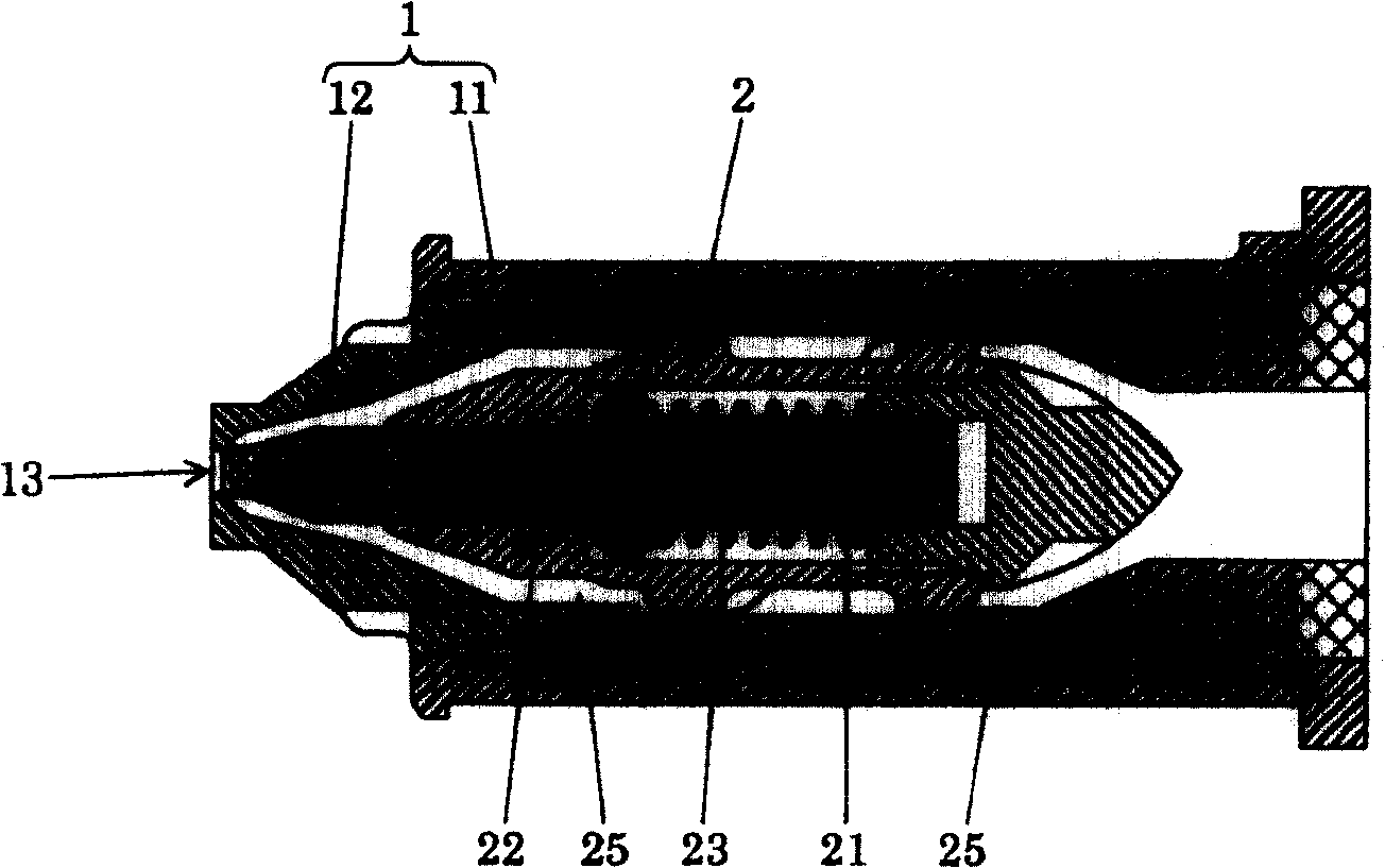
[0028] figure 1 Among them, the valve nozzle of the embodiment shown in the present invention is mainly composed of a valve nozzle body 1 and a gate opening and closing mechanism 2 arranged in the inner space of the valve nozzle body 1 .

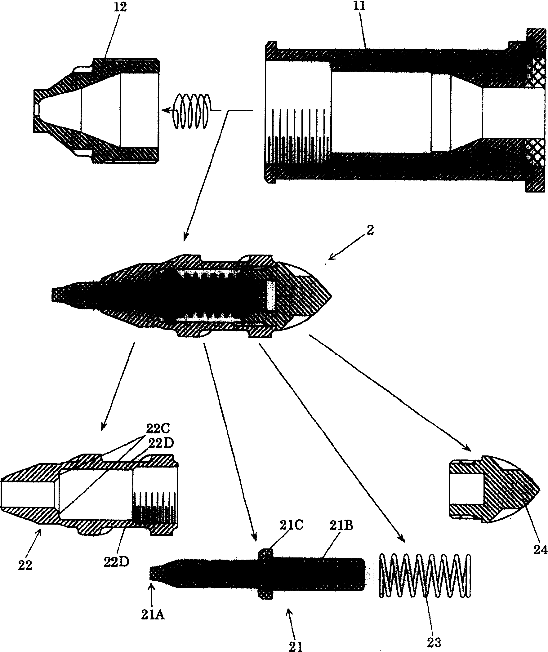
[0029] Valve nozzle body 1 such as figure 2 As shown, there are a nozzle base 11 and a nozzle tip 12 screwed to the nozzle base 11, and a gate 13 is formed at the front end of the nozzle tip.

[0030] Gate opening and closing mechanism 2 such as figure 2 As shown, it is composed of a piston 21, a torpedo-shaped part 22, a coil spring 23 and a cover 24, which are assembled into one body and arranged in the inner space of the valve nozzle body 1. The piston 21 has a head portion 21A and a shaft portion 21B formed continuously from the head portion 21A. The torpedo-like member 22 slidably supports the piston 21, guides the ...


PUM


Abstract

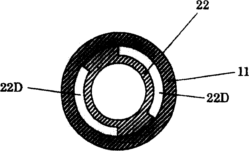
The valve nozzle according to the invention is constructed so that, the internal space of a valve nozzle main body is disposed with a gate opening and closing mechanism assembled by a piston, a torpedo shape component, a coil spring and a cover. The piston has a heat part and a shaft part. The torpedo shape component is disposed in the internal space of the nozzle head and slidably supports the piston and guides the piston and is provided with, on its outer circumferential surface, concaved grooves that are twisted with respect to a resin injection direction and serve as a plurality of wound resin flow channels. The coil spring presses the piston in the direction toward the gate. The cover closes the rear end of the torpedo and serves as a spring receiving part of the coil spring. when the resin pressure is at a predetermined value or less, the entire circumference of the circular section of the head part of the piston comes into contact with the inner wall of the gate of the nozzle head to close the resin flow channels, and when the resin pressure becomes a predetermined value or more, the head part withdraws from the gate to release the gate.

Description

technical field [0001] The present invention relates to a valve nozzle used in a synthetic resin molding machine, and more specifically, to a valve nozzle (valve nozzle) and a shut-off nozzle (shuttoofnozuru) used in hot runner molding. Background technique [0002] In Japanese Patent Application Laid-Open No. 57-163542 (hereinafter referred to as Document 1), a valve nozzle is disclosed. The structure is that the front end of the closing pin contacts the gate at the front end of the nozzle head to open and close the flow path. , the closing pin is forced toward the gate by the coil spring built in the airtight chamber. When the pressure of the resin reaches a certain value and the closing pin overcomes the elastic force of the coil spring, it moves toward the airtight chamber and the gate Open. [0003] In the valve nozzle described in Document 1, the residual stress near the gate is large when the resin flow path is closed, and the molded product is easily cracked at this...

Claims


Application Information

Patent Timeline
Patent Type & Authority Patents(China)
IPC IPC(8): B29C45/23B29C45/77B29C47/14B29C47/92B29C45/28B29C45/30B29C48/305B29C48/92
CPCB29C45/2806B29C2045/308B29C45/30H04M1/23H01H13/704H01H13/705
Inventor 斋藤敏男杜鸣
Owner FISA CORP
Learn More