
Micro-mechanical reciprocating membrane pump

A diaphragm pump and micro-mechanical technology, applied in mechanical equipment, liquid variable capacity machinery, pumps, etc., can solve the problems of uncertain dead time, large amount of fluid occupied, no inertial rectification, etc., and achieve consistent and reduced dwell time. Output pulsation and reduce the effect of occupying the volume of test solution

Inactive Publication Date: 2009-02-04
INST OF OPTICS & ELECTRONICS - CHINESE ACAD OF SCI
View PDF9 Cites 0 Cited by
  • Summary
  • Abstract
  • Description
  • Claims
  • Application Information

AI Technical Summary

Problems solved by technology

[0007] The micropump invented by Fred K. Foster et al. only considers the use of inertial rectification in the valve without moving parts, and does not perform inertial rectification on the entire flow process in the pump; for the application of biochemical analysis, it can obtain The pump pressure is still not high enough, and the output pulsation is still large
The pump cavity it adopts is the same as that of the existing micromechanical reciprocating diaphragm pump, which is a single-communication domain cavity, which occupies a large amount of fluid, the stagnation time of the fluid in it is uncertain, and the cleaning process is long.

Method used


Image

  • Micro-mechanical reciprocating membrane pump
  • Micro-mechanical reciprocating membrane pump
  • Micro-mechanical reciprocating membrane pump

Examples


Embodiment Construction

[0022] The present invention will be further described below in conjunction with accompanying drawing.

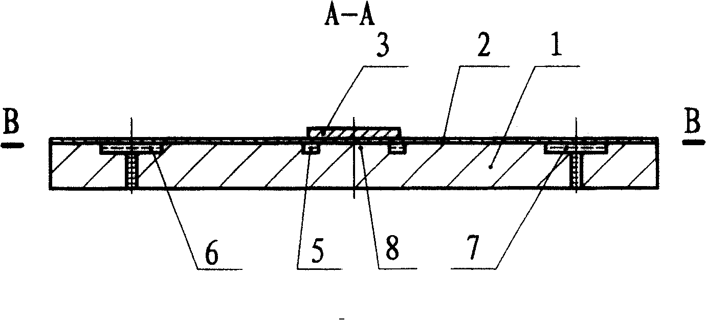
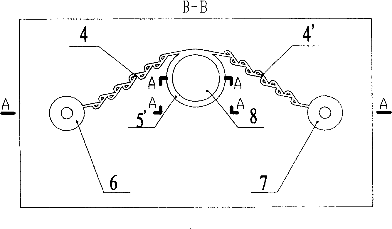
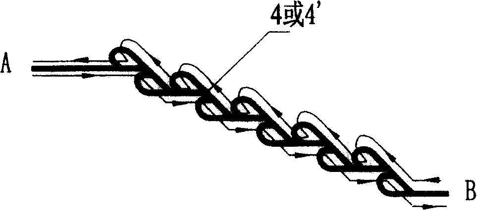
[0023] Such as figure 1 , figure 2 As shown, the micromechanical pump of the present invention is formed by bonding the pump body substrate 1 and the diaphragm 2 , and bonding the diaphragm 2 and the piezoelectric vibrator 3 . An annular groove 5' and a circular platform 8 are etched on the upper surface of the pump body substrate 1 in the port section, and an inertial annular cavity 5 is formed between the diaphragm 2; the inertial annular cavity 5 is connected to the input cavity through two inertial rectification channels 4, 4' 6. The output chamber 7 is connected. The port sections of the inertial rectification channels 4, 4' form a tangential positional relationship with the inertial annular cavity 5, and a port-to-portal positional relationship is formed between the ports of the two inertial rectification channels 4, 4'. In the inertial rectification channel 4 con...


PUM


Abstract

The present invention relates to micro mechanical reciprocating membrane pump, and is one kind of micro mechanical reciprocating membrane pump for biochemical microanalysis. The micro mechanical reciprocating membrane pump has piezoelectric driving device as driving source, which makes the membrane vibrate to force the pump cavity to suck in and pump out fluid reciprocally; inertial fairing flow channel as no-motion valve to make the flow damp in some direction greater than that in the other direction; inertial ring cavity to further increase the damp difference between two directions. The present invention has simple structure, can drive fluid containing relatively large grain, has no damage to cell or macro molecule in fluid, no dead volume and constant flow rate and other advantages, and is suitable for driving micro volume fluid in micro flow channel of cross section size in decades and hundreds microns.

Description

technical field [0001] The invention relates to a micromechanical reciprocating diaphragm pump, in particular to a micromechanical reciprocating diaphragm pump for microanalysis of biochemistry. Background technique [0002] Micromechanical reciprocating diaphragm pumps are widely used in microanalysis of biochemistry, which play the role of pumping samples, reagents, and buffers in the steps of sample introduction, analysis, and cleaning. The working principle of the general micromechanical reciprocating diaphragm pump is: connect the directional valve at both ends of the pump chamber, cover the diaphragm above the pump chamber, and the diaphragm reciprocates, forcing the pump chamber to suck fluid from one end and discharge fluid from the other end. Micromechanical reciprocating diaphragm pumps can be divided into two categories according to the use of one-way valves with moving parts and directional valves without moving parts. [0003] The advantage of using a micromech...

Claims


Application Information

Patent Timeline
Patent Type & Authority Patents(China)
IPC IPC(8): F04B17/00F04B19/20F04B43/04
Inventor 王皓姚汉民杜春雷焦玉中
Owner INST OF OPTICS & ELECTRONICS - CHINESE ACAD OF SCI
Learn More