
Energy consumption-free liquid charge pump for jack well

A technology with no energy consumption and pumping wells, applied in the field of liquid injection pumps, it can solve the problems that the motor cannot reach the pump pressure, increase the operating cost, and the energy consumption of the liquid injection pump is large, and achieve energy saving, low investment and simple structure. Effect

Active Publication Date: 2014-02-05
杨庆祝
View PDF6 Cites 0 Cited by
  • Summary
  • Abstract
  • Description
  • Claims
  • Application Information

AI Technical Summary

Problems solved by technology

At present, the liquid injection pumps on the existing oil production wells are all driven by electric power. Due to the uninterrupted work of the oil extraction machine and the liquid injection pump, the energy consumption of the liquid injection pump is relatively large, and there are many supporting facilities for the pump body. , takes up a lot of space, increases the operating cost, and the motor with low energy consumption often cannot reach the proper pump pressure, and cannot perform normal liquid injection

Method used


Image

  • Energy consumption-free liquid charge pump for jack well
  • Energy consumption-free liquid charge pump for jack well

Examples


Embodiment 1

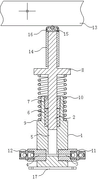
[0011] The non-energy-consuming liquid injection pump for pumping wells of the present invention is composed of a pump body 1, a plunger 2, a liquid inlet 3 and a liquid outlet 4. As shown in the figure, the lower part of the pump body 1 is provided with liquid inlets symmetrically on both sides 3 and the liquid outlet 4, one end of the plunger 2 is placed in the inner cavity 5 of the pump body 1, the liquid inlet 3 and the liquid outlet 4 are both connected to the inner cavity 5, and the upper part of the inner cavity 5 is provided with a packing 6 The gland 7 connected to the top of the pump body 1 by a screw is fixed, and the upper part of the other end of the plunger 2 is fixed with a pressure plate 8. A spring 10 is provided between the pressure plate 8 and the annular boss 9 on the upper part of the pump body 1. The upper screw port of the liquid inlet 3 is connected to the liquid inlet one-way valve body 11, and the screw port of the liquid outlet 4 is connected to the li...

Embodiment 2

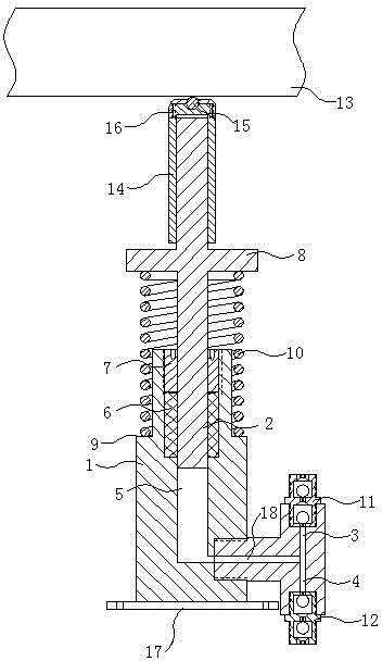
[0013] The non-energy-consuming liquid injection pump for pumping wells of the present invention is composed of a pump body 1, a plunger 2, a liquid inlet 3 and a liquid outlet 4, such as figure 2 As shown, the bottom of the pump body 1 is provided with a pump seat 17, the lower side of the pump body 1 is provided with a liquid inlet 3 and a liquid outlet 4, one end of the plunger 2 is placed in the inner cavity 5 of the pump body 1, and The liquid port 3 and the liquid outlet 4 are communicated with the inner cavity 5 of the pump body 1 through the communicating hole 18 in the valve body; the upper part of the inner cavity 5 is provided with a packing 6, and the packing 6 is provided with a gland 7 and the pump body 1 The top inner wall is screw-fastened, the middle and upper part of the plunger 2 is fixed with a pressure plate 8, a spring 10 is provided between the pressure plate 8 and the annular boss 9 on the upper part of the pump body 1, and the upper part of the plunger ...


PUM


Abstract

The invention relates to liquid charge pumps, in particular to an energy consumption-free liquid charge pump for a jack well. The liquid charge pump is formed by a pump body, a plunger, a liquid inlet and a liquid outlet; the liquid inlet is formed in one side of the lower part of the pump body, and the liquid outlet is formed in the other side of the pump body; one end of the plunger is arranged in the inner cavity of the pump body; the upper part of the inner cavity is fixed by a gland of which the packing is connected to the top of the pump body by a screw port; a platen is fixed at the upper part of the other end of the plunger; a spring is arranged between an annular boss at the upper part of the pump body and the platen; the upper screw port of the liquid inlet is connected with a liquid inlet check valve body, and the screw port of the liquid outlet is connected with a liquid outlet check valve body; the top of the plunger is slidably connected with a walking beam in the jack well. The liquid charge pump is powered and connected by the vertical reciprocation of the walking beam on a pumping unit, certain electric-driven supporting facilities are saved, and the energy consumption-free liquid charge pump has the characteristics that the size is small, the weight is light, the structure is simple, the flow is precisely adjusted by the rest energy of the pumping unit without consuming electric energy in the operation process, the cost is low and the like.

Description

Technical field [0001] The invention relates to a liquid injection pump, in particular to a non-energy-consuming liquid injection pump for oil pumping wells. Background technique [0002] In the oil field development process, the water from the water injection well is injected into the oil reservoir through a special injection pump to maintain or restore the oil layer pressure, so that the oil reservoir has a strong driving force, so as to improve the oil reservoir's production speed and recovery efficiency . At present, the liquid injection pumps on the existing oil production wells are all driven by electric drive. Due to the uninterrupted work of the oil extraction machine and the liquid injection pump, the energy consumption of the liquid injection pump is relatively large, and the pump body has more supporting facilities. , It occupies a large space and increases the operating cost, and the low-energy-consumption motor often fails to reach the due pump pressure and cannot b...

Claims


Application Information

Patent Timeline
Patent Type & Authority Applications(China)
IPC IPC(8): F04B17/00E21B43/20
Inventor 杨庆祝
Owner 杨庆祝
Learn More