
Welding robot multifunctional double-eye visual sensor and calibration method thereof

A welding robot and binocular vision technology, applied in welding equipment, welding accessories, instruments, etc., can solve the problems of reduced automation and intelligence of welding robots, single function, and inability to meet the accuracy at the same time

Inactive Publication Date: 2009-02-11
SHANGHAI JIAO TONG UNIV
View PDF6 Cites 3 Cited by
  • Summary
  • Abstract
  • Description
  • Claims
  • Application Information

AI Technical Summary

Problems solved by technology

At present, the relatively mature research at home and abroad is the visual sensing method using a fixed focal length camera, which has the disadvantage of a single function. It can only complete a specific welding work. The lens can complete the task of visual sensing
[0003] After searching the literature of the prior art, it was found that the Chinese patent application number: 200410067328.1, titled "Welding Robot Servo Binocular Vision Sensor" patent provides a vision sensor, the sensor is mainly composed of two CCD cameras, through image acquisition card and CCD camera to realize the acquisition of welding seam images. This device can collect the image information of the weld seam in real time, and the tracking accuracy can meet the requirements of welding seam tracking. However, the CCD camera uses a lens with a fixed focal length. The visual scenes and resolutions required for initial position guidance and weld seam tracking are different, so one lens cannot meet the accuracy of welding initial position guidance and weld seam tracking at the same time. If the sensing of the above two processes is required When the accuracy is very high, the lens of the camera needs to be replaced manually; at the same time, since the shooting angle of the camera is fixed, it is necessary to manually adjust the shooting angle of the camera when guiding the starting position of welding and tracking the welding seam. After the position of the camera is changed, it is necessary to re-calibrate the internal and external parameters of the camera, resulting in a reduction in the automation and intelligence of the welding robot.

Method used


Image

  • Welding robot multifunctional double-eye visual sensor and calibration method thereof

Examples


Embodiment Construction

[0021] The embodiments of the present invention are described in detail below in conjunction with the accompanying drawings: the present embodiment is implemented on the premise of the technical solution of the present invention, and detailed implementation methods and processes are provided, but the protection scope of the present invention is not limited to the following implementations example.

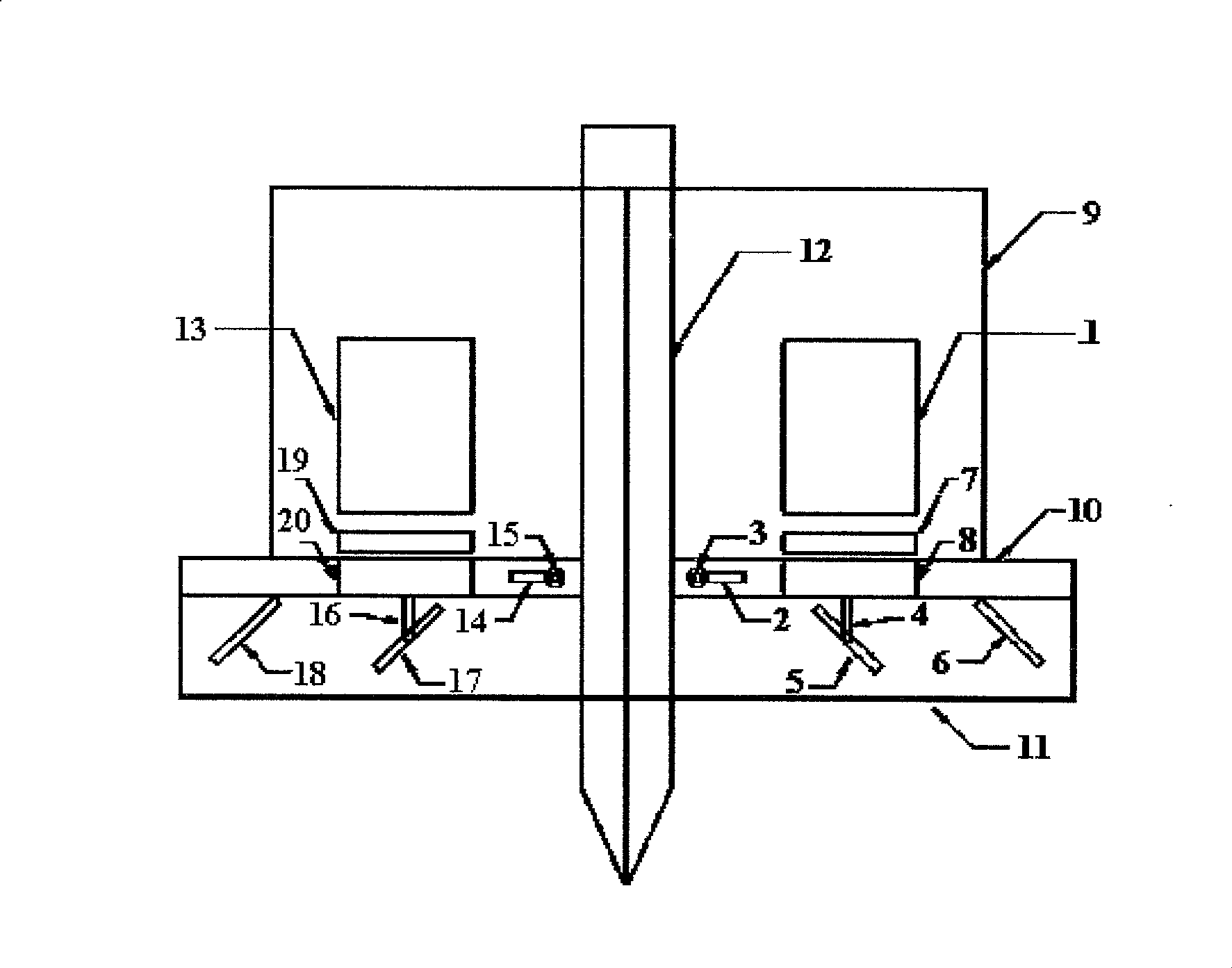
[0022] Such as figure 1 As shown, the multifunctional binocular vision sensor of the welding robot in this embodiment includes: the first camera 1, the second camera 13, the first and second pneumatic systems, the first and second light reduction and filter systems, the first and second reflectors System and mounting bracket; the first camera 1, the second camera 13, the first and second pneumatic systems, the first and second light reduction and filter systems and the first and second mirror systems are all fixed on the mounting bracket, the first camera 1. The first pneumatic sy...


PUM


Abstract

A multifunctional binocular vision sensor of welding robot and relative marking method comprise a camera, a dimming filtering system, an aerating system, a reflector system, and a mounting support, while the camera, aerated system and the dimming filtering system and the reflector system are all fixed on the mounting support, the camera, aerated system, a dimming filtering system, and reflector system are vertically arranged at one side of a welding gum from up to down, the camera and the dimming filtering system are coaxial. The invention also provides relative marking method, while the invention can meet the demands of guiding, welding seam track and quality control in welding process, with high accuracy and effect.

Description

technical field [0001] The invention relates to a device in the field of welding technology and a calibration method thereof, in particular to a multifunctional binocular vision sensor of a welding robot and a calibration method thereof. Background technique [0002] At present, there are various sensing methods used on welding robots. Among these sensing methods, the visual sensing method is favored by people because of the advantages of large amount of collected information, non-contact, fast, high precision and large detection range. The application of visual sensing technology in the field of welding robots is mainly to conduct research on the intelligent control of the welding process, such as the guidance of the initial welding position, the identification of the welding joint form, the visual tracking of the weld seam, and the penetration control. At present, the relatively mature research at home and abroad is the visual sensing method using a fixed focal length cam...

Claims


Application Information

Patent Timeline
Patent Type & Authority Patents(China)
IPC IPC(8): B25J19/00B23K28/00B23K9/32G03B29/00G02B17/06
Inventor 孔萌石繁槐林涛苏冲岗陈善本
Owner SHANGHAI JIAO TONG UNIV
Learn More