Liquid crystal display device
A liquid crystal display and backlight module technology, applied in static indicators, instruments, nonlinear optics, etc., can solve the problems of expanding the volume of backlight modules, the inability of liquid crystal displays to achieve high color saturation, and affecting the quality of high-color full-color display
- Summary
- Abstract
- Description
- Claims
- Application Information
AI Technical Summary
Problems solved by technology
Method used
Image

Examples
no. 1 example
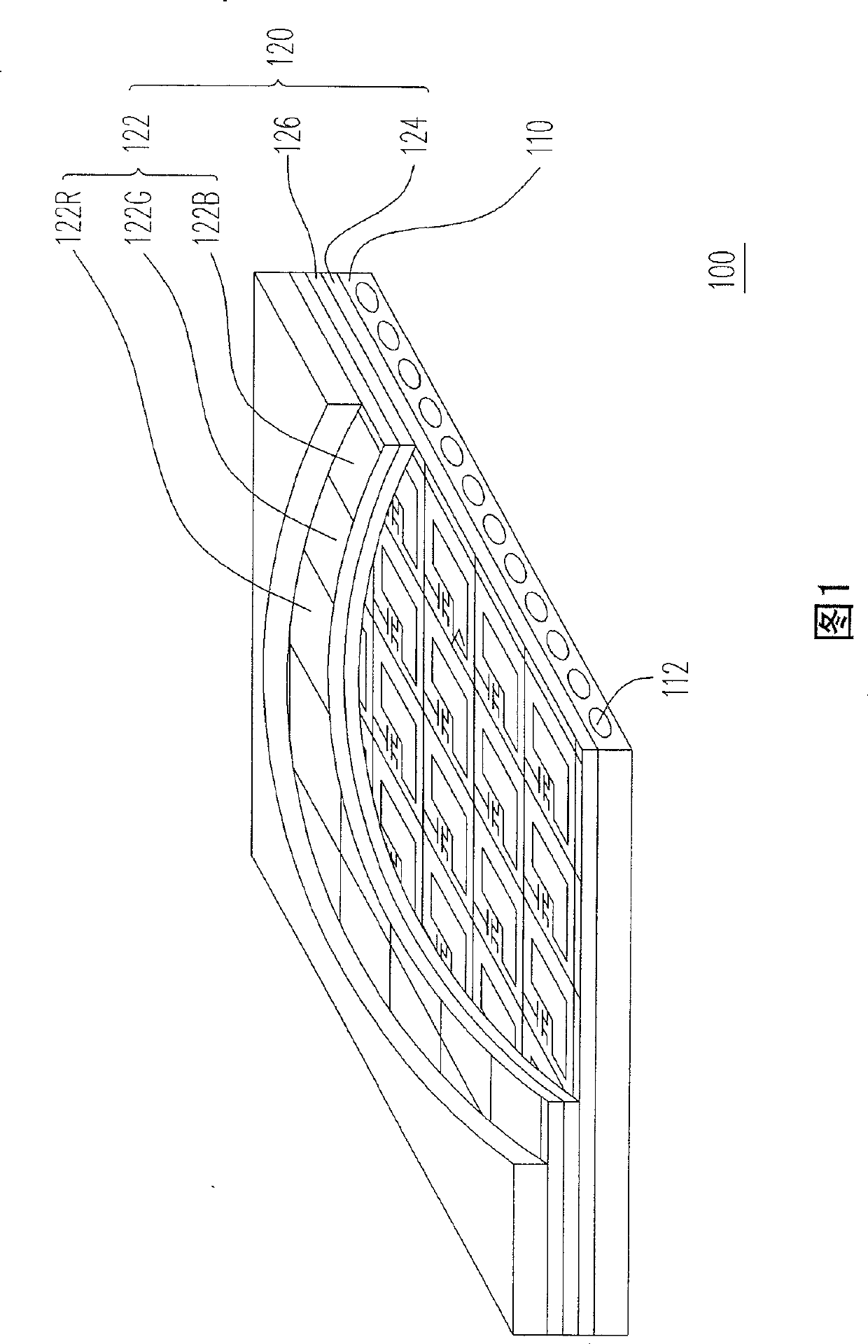
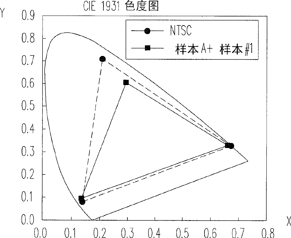
[0075] The color filter substrate used in the first embodiment of the present invention is sample A, and the backlight module selected to match it is sample #1.
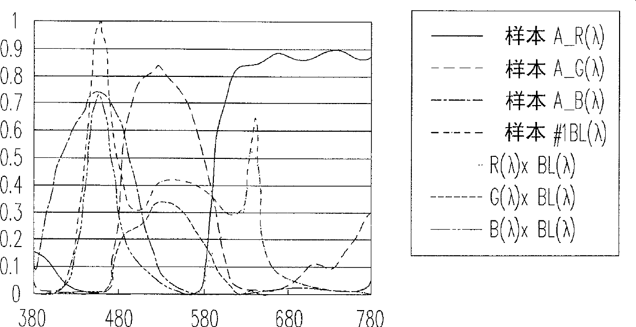
[0076] Figure 2A It is a spectrum diagram of the light source emitted by the white light point light source used in the first embodiment of the present invention. Among them, R(λ), G(λ), and B(λ) respectively represent the three brightness peaks of red light, green light and blue light in the spectrum emitted by the white light point light source, and BL(λ) represents that the light of each wavelength is normalized Brightness after normalization.
[0077] In the combination of the color filter substrate and the backlight module used in the first embodiment of the present invention, the sum of the products of the transmittance spectrum of the color filter substrate and the spectrum of the backlight module within the specified wavelength range is calculated as follows:
[0078] (1A) Σ ...
no. 2 example
[0088] The color filter substrate used in the second embodiment of the present invention is sample B, and the backlight module selected to match it is sample #2.
[0089] Figure 3A It is a spectrum diagram of the light source emitted by the white light point light source used in the second embodiment of the present invention. Among them, R(λ), G(λ), and B(λ) respectively represent the three brightness peaks of red light, green light and blue light in the spectrum emitted by the white light point light source, and BL(λ) represents that the light of each wavelength is normalized Brightness after normalization.
[0090] In the combination of the color filter substrate and the backlight module used in the second embodiment of the present invention, the sum of the products of the transmittance spectrum of the color filter substrate and the spectrum of the backlight module within the specified wavelength range is calculated as follows:
[0091] (1B) Σ ...
no. 3 example
[0099] The color filter substrate used in the third embodiment of the present invention is sample C, and the backlight module selected to match it is sample #3.
[0100] Figure 4A It is a spectrum diagram of the light source emitted by the white light point light source used in the third embodiment of the present invention. Among them, R(λ), G(λ), and B(λ) respectively represent the three brightness peaks of red light, green light and blue light in the spectrum emitted by the white light point light source, and BL(λ) represents the brightness of each wavelength of light when it is detected Brightness after normalization.
[0101] In the combination of the color filter substrate and the backlight module used in the third embodiment of the present invention, the sum of the products of the transmittance spectrum of the color filter substrate and the spectrum of the backlight module within the specified wavelength range is calculated as follows:
[0102] (1C) ...
PUM
 Abstract
Description
Claims
Application Information
 - R&D
- Intellectual Property
- Life Sciences
- Materials
- Tech Scout
- Unparalleled Data Quality
- Higher Quality Content
- 60% Fewer Hallucinations
Browse by: Latest US Patents, China's latest patents, Technical Efficacy Thesaurus, Application Domain, Technology Topic, Popular Technical Reports.
© 2025 PatSnap. All rights reserved.Legal|Privacy policy|Modern Slavery Act Transparency Statement|Sitemap|About US| Contact US: help@patsnap.com