Bidirectional optical communication module

A communication module and bi-directional light technology, which is applied in optics, light guides, optical components, etc., can solve problems such as performance problems and cost increases of bi-directional optical communication modules

Inactive Publication Date: 2009-03-18
SHARP KK
View PDF6 Cites 0 Cited by
  • Summary
  • Abstract
  • Description
  • Claims
  • Application Information

AI Technical Summary

Problems solved by technology

Therefore, the cost will increase, and there are also problems in the performance of the bidirectional optical communication module.

Method used


Image

  • Bidirectional optical communication module
  • Bidirectional optical communication module
  • Bidirectional optical communication module

Examples


Embodiment Construction

[0058] (Embodiment 1)

[0059] Below, refer to Figure 1 ~ Figure 1 5. One embodiment of the present invention will be described.

[0060] In addition, the present invention is not limited to the following embodiments, and various changes can be made within the scope of the present invention.

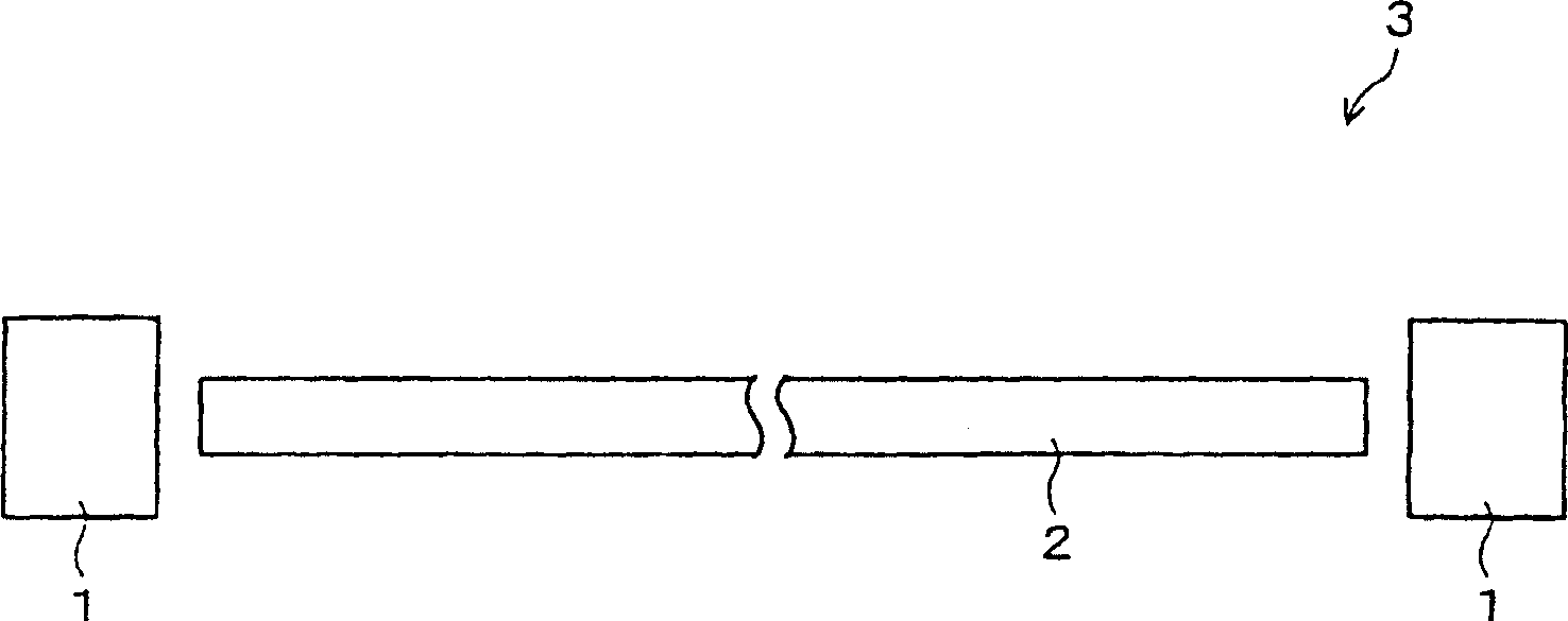
[0061] figure 1 It is a structure showing a bidirectional optical communication line. The bidirectional optical communication line 3 includes an optical fiber 2 for bidirectionally transmitting modulated light suitable for transmission according to a data signal to be transmitted. In addition, the bidirectional optical communication line 3 has a bidirectional optical communication module 1 at both ends of the optical fiber 2 . In addition, the optical fiber 2 refers to a type of optical communication path element having an optical communication path through which an optical signal passes.

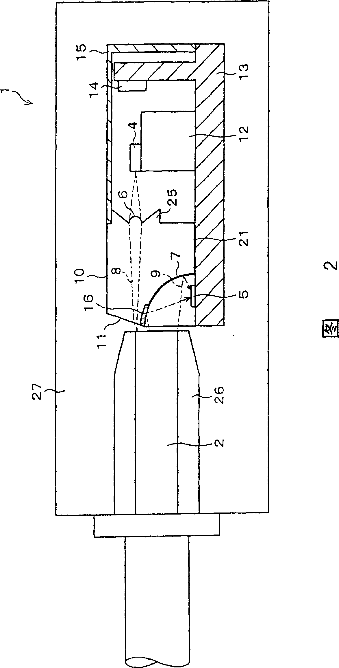
[0062] Fig. 2 shows a bidirectional optical communication module of this embodiment. An op...


PUM


Abstract

In a bidirectional optical communications module capable of all-dual-mode communications using a single optical fiber, interference due to internally scattered light is reduced by forming a diverging area on a periphery of a transmission lens and providing a thin film reflection mirror which collects incoming light. A inexpensive, compact bidirectional optical communications module can be offered with reduced interference between outgoing and incoming light, especially, interference due to internally scattered light.

Description

technical field [0001] The present invention relates to a bidirectional optical communication module that utilizes an optical communication path element and an optical signal to perform bidirectional communication, and more specifically relates to a module that can be used in home communication, communication between electronic devices, and LAN (Local Area Network, local area network), etc. bidirectional optical communication module. Background technique [0002] With the development of an information society, attention is being paid to utilizing network technologies having optical communication path elements in optical communication paths through optical signals. An optical communication path element having an optical communication path through which an optical signal passes refers to an optical fiber or a plastic optical fiber. In particular, in recent years, POF has been applied to communication in the home and communication between electronic devices along with the redu...

Claims


Application Information

Patent Timeline
Patent Type & Authority Patents(China)
IPC IPC(8): G02B6/42H01L31/12H04B10/24
CPCG02B6/4246G02B6/4214G02B6/4206H04B10/2504H04B10/25891
Inventor 藤田英明石井赖成田村壽宏
Owner SHARP KK
Why Eureka
Try Eureka