Methods and apparatus for cross-talk and jitter reduction in multi-beam optical disks

a multi-beam optical disk and cross-talk technology, applied in the direction of digital signal error detection/correction, instruments, recording signal processing, etc., can solve the problems of minor differences in the spacing of beams, difficult and expensive design and manufacture of drives, and the ability of optical disks to present new design challenges, so as to reduce cross-talk and jitter. , the effect of reducing cross-talk and jitter

Inactive Publication Date: 2005-09-06
XYLON LLC
View PDF34 Cites 5 Cited by
  • Summary
  • Abstract
  • Description
  • Claims
  • Application Information

AI Technical Summary

Benefits of technology

[0019]Advantageously, using the split detectors reduces cross-talk and jitter considerably when the track offset is not a large fraction of the track pitch. Cross-talk cancellation algorithms are used together with the split detectors to significantly reduce cross-talk and jitter when the track offset is a large fraction of the track pitch. Additionally, the cross-talk and jitter reduction is performed without requiring additional circuitry connected to the multi-optical pickup assembly.

Problems solved by technology

Higher disk rotational speeds, however, place increased demands on the optical and mechanical subsystems within the optical disk drive, create greater vibration, and may make such drivers more difficult and expensive to design and manufacture.
Implementation of simultaneous multiple track reading capability for optical disks presents new design challenges.
In addition, manufacturing tolerances may lead to minor differences in the magnification of an optical pickup assembly, leading to minor differences in the spacing of the beams.
Such errors arising from magnification errors, track pitch variations, and large track offsets may result in cross-talk, which occurs when a portion of the light beam reflected from one track is being read by a photodetector associated with an adjacent track, and jitter, which occurs when the sampling of the digital signal read from a track is not done on time.
The presence of cross-talk and jitter result in poor signals being read from the disk.
At present, there are no systems in place that can reduce both cross-talk and jitter without requiring additional circuitry connected to the multi-beam optical pickup assembly.
In addition, the current systems are not able to reduce both cross-talk and jitter that occur due to large track offsets.

Method used


Image

  • Methods and apparatus for cross-talk and jitter reduction in multi-beam optical disks
  • Methods and apparatus for cross-talk and jitter reduction in multi-beam optical disks
  • Methods and apparatus for cross-talk and jitter reduction in multi-beam optical disks

Examples


Embodiment Construction

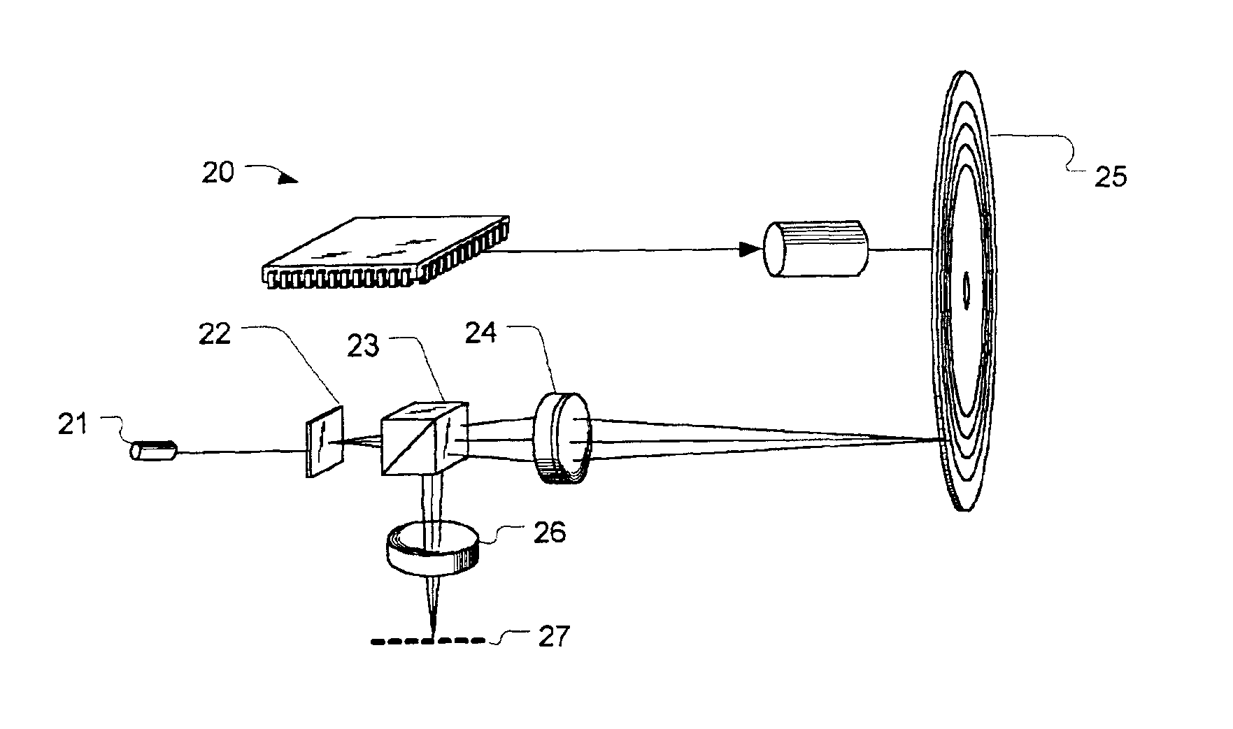
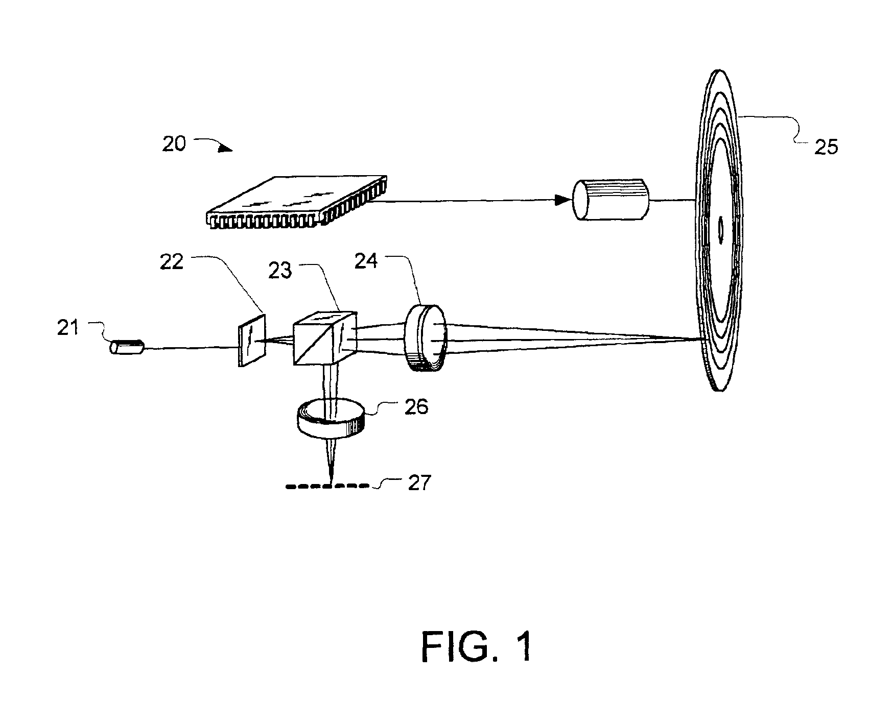
[0030]Referring to FIG. 1, a schematic view of a simplified multi-beam optical pickup suitable for use in the present invention is described. Optical pickup 20 may be used for reading optical disk 25, which may be, for example, either a CD format or a DVD format disk. Individual components of optical pickup assembly 20 may comprise elements used in previously known optical disk readers. Light from light source 21, typically a laser diode, is directed to grating 22 which splits the light into multiple beams. The multiple beams pass through beam splitter 23 and directed to optical disk 25. Objective lens 24 is adjusted by a servo mechanism to keep the light beams focused on the surface of optical disk 25.

[0031]Optical disk 25 contains a reflective layer in which the data is recorded. Typically the data is recorded in the form of pits (or bumps) in the reflective layer. Alternatively, some recordable optical disks use physical or chemical properties of the reflective layer material, su...


PUM

PropertyMeasurementUnit
widthaaaaaaaaaa
thresholdaaaaaaaaaa
thresholdaaaaaaaaaa

Abstract

Methods and apparatus are provided for reducing cross-talk and jitter caused by track offsets in multi-beam optical disks. The method and apparatus involve using split detectors and cross-talk cancellation algorithms in the multi-element photodetector of the multi-beam optical disks. The cross-talk cancellation algorithms are applied according to the value of the track offset as a function of the track pitch.

Description

FIELD OF THE INVENTION[0001]The present invention relates generally to multi-beam optical disk drives which simultaneously read multiple tracks of an optical disk. More specifically, the present invention provides methods and apparatus for reducing cross-talk and jitter caused by track offsets in multi-beam optical disks.BACKGROUND OF THE INVENTION[0002]Due to their high storage density, long data retention life, and relatively low cost, optical disks have become the predominant media format for distributing information. The compact disk (CD) format was developed and marketed for the distribution of musical recordings and has replaced vinyl records. High-capacity, read-only data storage media, such as CD-ROM and DVD-ROM, have become prevalent in the personal computer field, and the DVD format may soon replace videotape as the distribution medium of choice for video information.[0003]Relatively inexpensive optical disk writers and writable optical media are now available, making opti...

Claims


Application Information

Patent Timeline
Patent Type & Authority Patents(United States)
IPC IPC(8): G11B7/00G11B7/005G11B7/13G11B7/14
CPCG11B7/005G11B7/131G11B7/133G11B7/14
Inventor FINKELSTEIN, KOBYROGERS, STEVEN R.KOSOBURD, TATIANA TANIAKEDMI, JOSEPH
Owner XYLON LLC
Why Eureka
Try Eureka