Moire fringes adjusting method for holographic grating making optical path

A holographic grating and Moiré fringe technology, applied in optics, optical components, instruments, etc., can solve the problems of high processing cost, affecting the quality of holographic grating, and difficult to eliminate the processing traces of aspheric devices, and achieve the effect of convenient and fast online detection.

Inactive Publication Date: 2009-03-18
SUZHOU UNIV
View PDF4 Cites 0 Cited by
  • Summary
  • Abstract
  • Description
  • Claims
  • Application Information

AI Technical Summary

Problems solved by technology

Aspherical lenses or off-axis parabolic mirrors are generally used as optical devices for collimating the optical path. Their processing costs are relatively high, and the auxiliary equipment for optical path adjustment is complex and expensive, and the processing traces of aspheric devices are difficult to eliminate. This processing trace will affect the holographic grating. quality

Method used


Image

  • Moire fringes adjusting method for holographic grating making optical path
  • Moire fringes adjusting method for holographic grating making optical path
  • Moire fringes adjusting method for holographic grating making optical path

Examples


Embodiment Construction

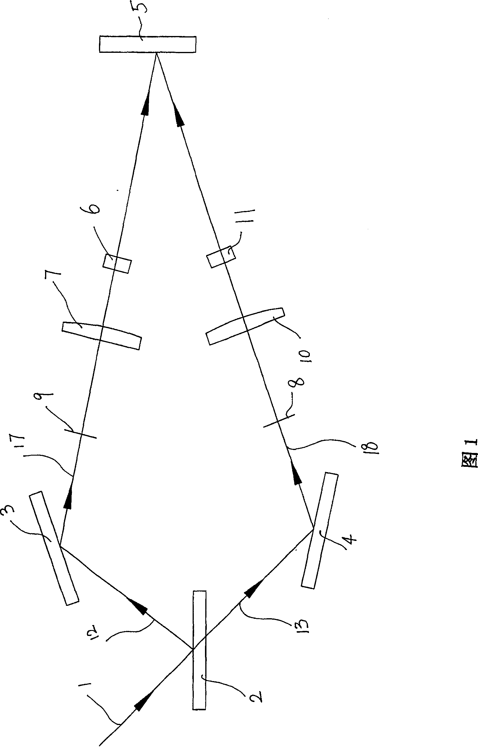
[0029] As shown in Figure 1, a method for adjusting moiré fringes in the optical path of a holographic grating comprises the following steps:

[0030] a. The beam splitter 2 divides the laser light 1 into object light 12 and reference light 13. The object light 12 is reflected by the main reflector 3 to form the main reflective light 17. The reference light 13 is reflected by the reference reflector 4 to form the reference reflective light 18. , both the main reflected light 17 and the reference reflected light 18 are irradiated on the holographic recording plate 5;

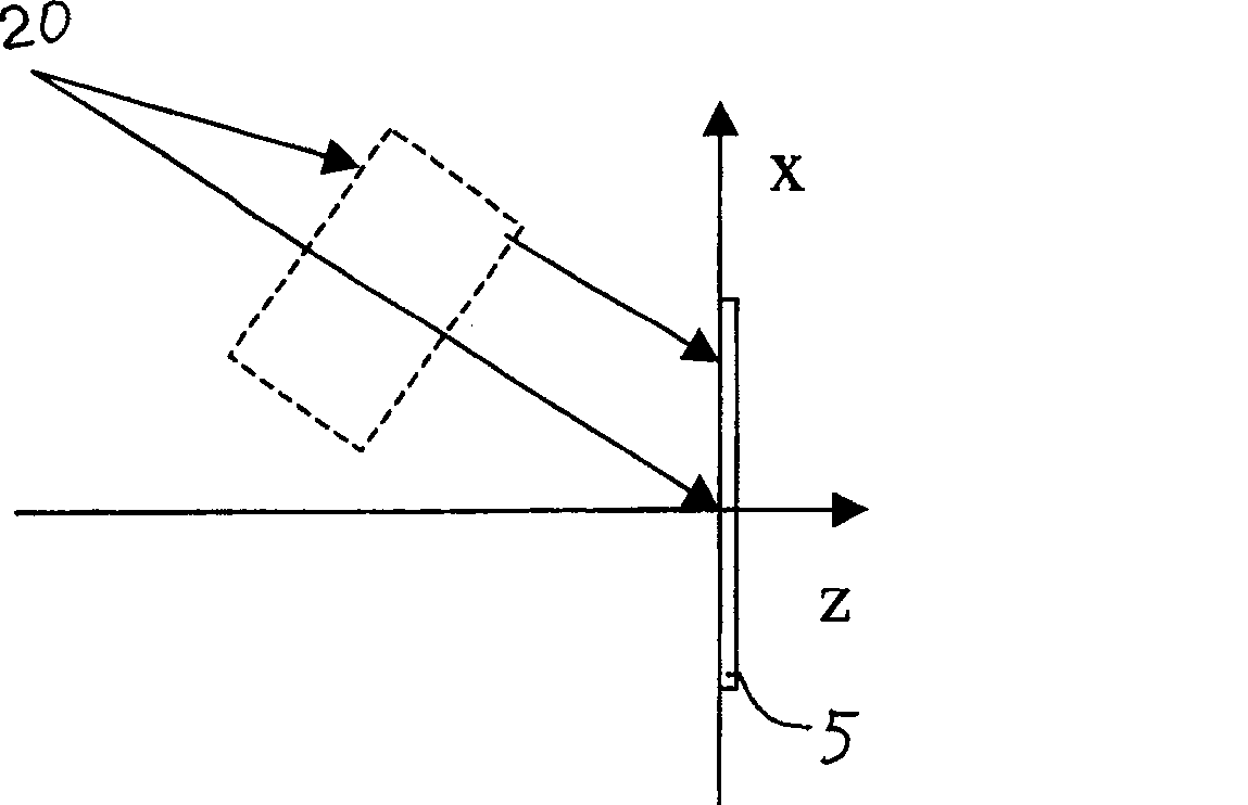
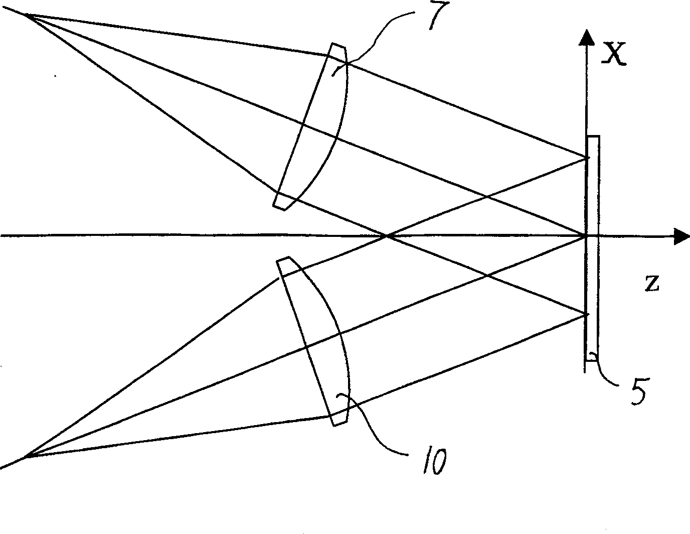
[0031] b. Adjust the positions of the main mirror 3, the reference mirror 4, and the holographic recording plate 5, so that the main reflected light 17 and the reference reflected light 18 are symmetrically incident on the holographic recording plate 5, and the main reflected light 17 and the reference reflected light 18 are recorded in the hologram. The incident angles on plate 5 all satisfy the formula ...


PUM


Abstract

The invention relates to a Mohr pattern adjust method of preparing optical path of holographic grating. Wherein, it uses spherical convex lens as collimator, uses Mohr pattern adjust method to detect the preparing optical path of plane holographic grating. Therefore, the axial and off-axis adjust errors in traditional optical path adjust method can be effectively eliminated; and the wave aberration of prepared pulse compress grating can be reduced most; and it can be used in other general grating.

Description

technical field [0001] The invention mainly relates to a method for adjusting moiré fringes, in particular to a method for adjusting moiré fringes in an optical path for making a holographic grating. Background technique [0002] Plane-parallel and equally-spaced stripe holographic grating is an important diffractive optical element, which is used in spectroscopic instruments, fiber grating phase masks, pulse compression gratings in inertial confinement fusion (ICF), X-ray spectroscopic gratings, etc., and its application fields extremely broad. The optical path for making the grating usually has two spherical wave interference optical paths equidistant from the recording material or two collimated parallel light interference optical paths using transmissive or reflective optical elements. The spherical wave optical path is suitable for small area or low aberration requirements, while the aberration-eliminating collimation optical path must be used for large area and high a...

Claims


Application Information

Patent Timeline
Patent Type & Authority Patents(China)
IPC IPC(8): G03H1/04G02B5/32
Inventor 吴建宏李朝明张伟刘全陈新荣胡祖元
Owner SUZHOU UNIV
Why Eureka
Try Eureka