Valve for controlling fluid

A technology for controlling fluids and valve housings, applied to fuel injection devices with piezoelectric elements or magnetostrictive elements, engine components, machines/engines, etc., can solve disadvantages and other problems, and achieve the effect of low cost and simple operation

Inactive Publication Date: 2009-04-08
ROBERT BOSCH GMBH
View PDF5 Cites 0 Cited by
  • Summary
  • Abstract
  • Description
  • Claims
  • Application Information

AI Technical Summary

Problems solved by technology

[0004] The disadvantage of this known prior art is that, due to this type of construction, unfavorable force conditions occur at the intersection with the bore of the actuator chamber and between the conical seals

Method used


Image

  • Valve for controlling fluid
  • Valve for controlling fluid
  • Valve for controlling fluid

Examples


Embodiment Construction

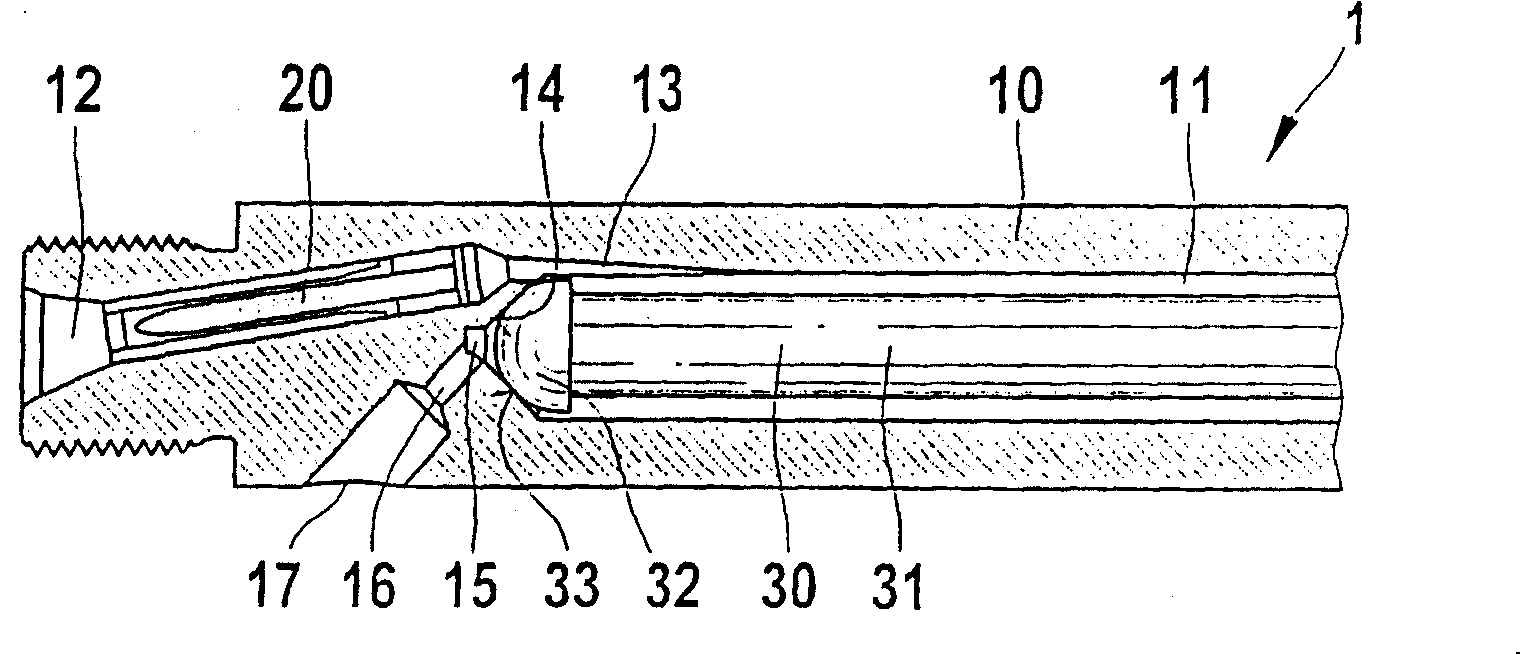
[0019] figure 1 Shown is a valve 1 for controlling a fluid, in particular diesel fuel, which is part of a common rail injector.

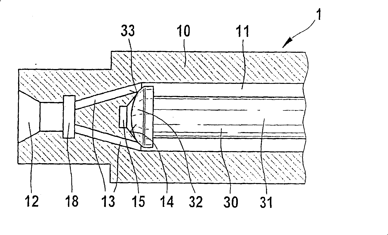
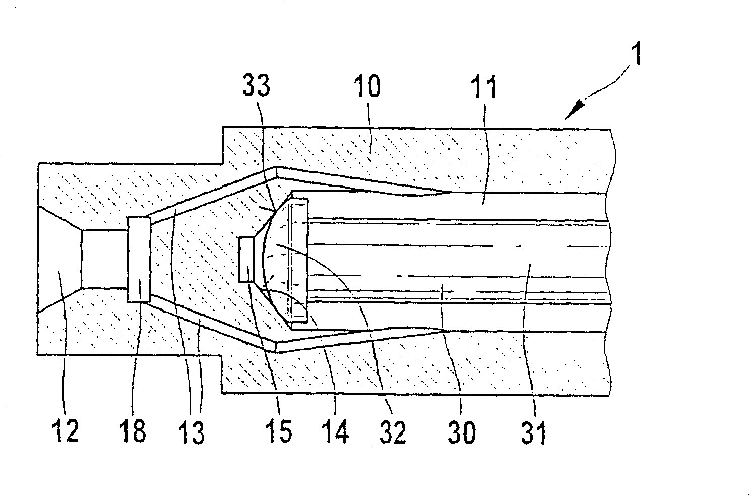
[0020] The valve 1 has a valve housing 10 in which extends in the longitudinal direction a pressure bore which forms an actuator chamber 11 . An actuator 30 is supported in the actuator chamber 11 and has a support 31 and an actuator head 32 . The actuator chamber 11 is sealed at its one end against a cable gland 17 by means of a conical seal. The conical seal is formed by means of a conical surface 14 at the end of the actuator chamber 11 and an annular sealing surface 33 corresponding to the conical surface on the actuator top 32 .

[0021] The valve housing 10 also has a high-pressure inlet 12 , which is connected to a high-pressure accumulator (not shown here) for liquid fuel. According to the prior art, fuel under high pressure is supplied laterally to the actuator chamber 11 of the valve housing 10 via an inlet opening 13 . Here, it can be...


PUM


Abstract

The invention relates to a valve (1) for controlling liquids, comprising a valve housing (10) having an actuator chamber (11) and a laterally arranged inlet hole (13) that is connected to a high pressure inlet (12), wherein the actuator chamber (11) has an actuator (30) with a plunger (31) and a round end (32), wherein the actuator chamber (11) has a taper gasket that is configured by means of a conical surface (14) on the end of the actuator chamber (11) and a matching annular sealing surface (33) on the round end (32) of the actuator, wherein a cable outlet (17) can be sealed off with the taper gasket. The actuator chamber (11) has at least another inlet hole (13). This makes it possible to achieve a more even power distribution to the actuator (30).

Description

technical field [0001] The invention relates to a valve for controlling a fluid. Background technique [0002] Such a valve is known from EP 0 192 241 . In this case, in particular the injection valves in common rail injection systems are provided with servo valves for controlling the fluid flow. To fuel the internal combustion engine, so-called accumulator injection systems are used, in which systems work with very high injection pressures. Such injection systems are known as common rail injection systems for diesel engines and HPDI injection systems for gasoline engines. In these injection systems, fuel is conveyed via high-pressure pumps into a common high-pressure accumulator, from where the injection valves on the individual cylinders are supplied with fuel. The opening and closing of the injection valves is generally controlled electronically. [0003] It is known from DE 196 50 865 A1 that a fuel injector has a high-pressure connection which opens laterally into t...

Claims


Application Information

Patent Timeline
Patent Type & Authority Patents(China)
IPC IPC(8): F02M51/06F02M59/46F02M55/00F02M61/16F02M63/00
CPCF02M2200/16F02M47/027F02M51/0603F02M55/002F02M55/005F02M63/0026F02M61/165F02M2200/21
Inventor 乔瓦尼·费拉罗卡西姆-梅利赫·哈穆特库
Owner ROBERT BOSCH GMBH
Why Eureka
Try Eureka